
VIP member
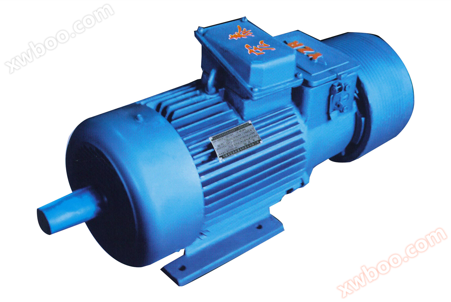
YZRW eddy current brake lifting metallurgical motor
Product Overview: The 1YZRW series eddy current brake wound rotor three-phase asynchronous motor for lifting and metallurgy is composed of a YZR serie
Product details

Product Overview:
Series of eddy current brake wound rotor three-phase asynchronous motors for lifting and metallurgy
The YZRW series eddy current brake wound rotor three-phase asynchronous motor for lifting and metallurgy is composed of a YZR series motor and an eddy current brake installed on its secondary shaft extension. It integrates both driving and speed regulation functions: it has stable low-speed speed regulation characteristics and advantages such as no loss of control and reliable operation.
The eddy current brake motor can operate normally under the following environmental conditions:
(1) The temperature of the cooling medium shall not exceed 60 ℃ (for motors with H-class insulation) or 40 ℃ (for motors with F-class insulation);
(2) Altitude not exceeding 1000m;
(3) Frequent and significant mechanical vibrations and impacts.
The eddy current brake motor is a derivative product of humid tropical climate environment, and its winding and surface protective layer have undergone special impregnation and treatment. Except for the provisions in Article 2, it can operate normally under the following environmental conditions.
(1) At 25 ℃, the monthly average maximum relative humidity of the wettest month is 90%;
(2) Minimum ambient air humidity -15 ℃;
(3) Frequent starting and braking.
The guaranteed value of the ratio of the maximum torque to the rated torque of the eddy current brake motor under rated voltage and reference working mode shall not be lower than the specifications in the following table:
|
Rated power KW |
Maximum torque Tb/rated torque TN |
| ≤5.5 | 2.3 |
| >5.5~11 | 2.5 |
| >11 | 2.8 |
Meaning of Motor Model 5:

Work schedule and technical data:
Work schedule: The benchmark work of the eddy current brake motor is S3, with a benchmark load duration of 40% for the motor and 15% for the eddy current brake. Each work cycle is 10 minutes. The rated power and flywheel torque (GD2) of the eddy current brake motor during reference operation. The rated braking torque and limited braking torque of the rotor open circuit voltage and its eddy current brake, as well as the corresponding relationship between the flywheel torque (GD2) and the machine base number, are shown in the table below
| frame size | 112M | 132M1 | 132M2 | 160M1 | 160M2 | 160L | 180L | 200L | 225M | 250M1 | 250M2 | 280S | 280M | ||
| vortex flow manufacture move electricity move machine |
1000 r/min |
power KW |
1.5 | 2.2 | 3.7 | 5.5 | 7.5 | 11 | 15 | 22 | 30 | 37 | 45 | 55 | 75 |
| Jm1 Kg.m2 |
0.03 | 0.06 | 0.07 | 0.12 | 0.15 | 0.2 | 0.39 | 0.67 | 0.84 | 1.52 | 1.78 | 2.35 | 2.86 | ||
| Open circuit of rotor voltage |
100 | 132 | 185 | 138 | 185 | 250 | 218 | 200 | 250 | 250 | 290 | 280 | 370 | ||
| 750 r/min |
power KW |
- | - | - | - | - | 7.5 | 11 | 15 | 22 | 30 | 37 | 45 | 55 | |
| Jm1 Kg.m2 |
- | - | - | - | - | 0.20 | 0.39 | 0.67 | 0.82 | 1.52 | 1.79 | 2.35 | 2.86 | ||
| Open circuit of rotor voltage |
- | - | - | - | - | 205 | 172 | 178 | 232 | 272 | 335 | 305 | 360 | ||
| 600 r/min |
power KW |
- | - | - | - | - | - | - | - | - | - | - | 37 | 45 | |
| Jm1 Kg.m2 |
- | - | - | - | - | - | - | - | - | - | - | 3.58 | 3.98 | ||
| Open circuit of rotor voltage |
- | - | - | - | - | - | - | - | - | - | - | 150 | 172 | ||
| vortex flow manufacture move electricity move machine |
vortex flow manufacture move device |
Rated braking Torque N · m |
7 | 18 | 64 | 118 | 170 | 235 | 390 | 590 | |||||
| rated speed r/min |
100 | 100 | 100 | 100 | 100 | 100 | 100 | 100 | |||||||
| Limited braking Torque N · m |
26 | 64 | 196 | 245 | 390 | 540 | 785 | 1180 | |||||||
| GD2 kg·m2 |
0.13 | 0.3 | 0.6 | 1.3 | 1.9 | 2.9 | 5.3 | 8.8 | |||||||
Structure of electric motor:
Protection level: Eddy current brake motors for general environments are IP44, eddy current brake motors for metallurgical environments are IP54, and eddy current brakes are IP00. Cooling method:
| code name | Available machine base numbers | Remarks |
| IC0041 | 112—132 | Fully enclosed motor, casing cooling, no external fan |
| IC0141 | 160—315 | Fully enclosed fan cooled motor with a cooler on the casing |
|
Structure and installation form |
code name | Manufacturing scope (machine base number) |
 |
IM1001 | 112~160 |
| IM1003 | 180~280 | |
 |
IM3011 | 112~160 |
| IM3013 | 180~280 |

Installation and external dimensions:
YZRW series IM1001 and IM1003 horizontally installed eddy current brake motors with base feet and end caps without flanges


|
frame size |
installation dimensions | Overall dimensions | ||||||||||||||||||||||||||||||
| A | A/2 | B | 左右 B difference |
C | 左右 C difference |
D | D1 | E | E1 | F(N9) | G | H | CA | K | BB | AB | AC | HD | L | D2 | LA | |||||||||||
| basic size |
limit bias |
basic size |
limit bias |
basic size |
limit bias |
basic size |
limit bias |
basic size |
limit bias |
basic size |
basic size |
limit bias |
basic size |
basic size | limit bias |
basic size | limit deviation | basic size | limit deviation | basic size | basic size | limit deviation | ||||||||||
| 112M | 190 | ±0.7 | 98 | ±0.5 | 140 | ±0.7 | ±0.7 | 70 | ±2.0 | 0.3 | 32 | +0.018 +0.002 |
﹣ | 80 | ±0.37 | ﹣ | 10 | 0 -0.036 |
27 | 0 -0.20 |
112 | 0 -0.50 |
283 | 12 | +0.42 0 |
235 | 250 | 245 | 330 | 698 | Φ220 | 125 |
| 132M | 216 | 108 | 178 | 89 | 38 | 33 | 132 | 260 | 275 | 285 | 360 | 775 | Φ260 | 145 | ||||||||||||||||||
| 160M | 254 | ±1.05 | 127 | ±0.75 | 210 | ±1.05 | ±1.05 | 108 | ±3.0 | 0.45 | 48 | 110 | ±0.43 | ﹣ | 14 | 0 -0.043 |
42.5 | 160 | 317 | 15 | 290 | 320 | 325 | 420 | 916 | Φ315 | 171 | |||||
| 160L | 254 | 335 | 960 | |||||||||||||||||||||||||||||
| 180L | 279 | 139.5 | 279 | 121 | 55 | M36×3 | 82 | 19.9 | 180 | 319 | 380 | 360 | 360 | 460 | 1070 | Φ335 | 241 | |||||||||||||||
| 200L | 318 | 159 | 305 | 133 | 60 | M42×3 | 140 | ±0.5 | 105 | 16 | 21.4 | 200 | 375 | 19 | +0.52 0 |
400 | 405 | 405 | 510 | 1175 | Φ395 | 222 | ||||||||||
| 225M | 356 | 178 | 311 | 149 | ±4.0 | 65 | 23.9 | 225 | 425 | 410 | 455 | 430 | 545 | 1270 | Φ445 | 245 | ||||||||||||||||
| 250M | 406 | ±1.40 | 203 | ±1.00 | 349 | ±1.40 | ±1.40 | 168 | 0.60 | 70 | M48×3 | 18 | 25.4 | 250 | 488 | 24 | 510 | 515 | 480 | 605 | 1455 | Φ495 | 310 | |||||||||
| 280S | 457 | 228.5 | 368 | 190 | 85 | M56×4 | 170 | 130 | 20 | 0 -0.052 |
31.7 | 280 | 0 -1.0 |
500 | 530 | 575 | 535 | 665 | 1569 | Φ555 | 341 | |||||||||||
| 280M | 419 | 580 | 1620 | |||||||||||||||||||||||||||||
| 315S | 508 | ±1.40 | 254 | ±1.00 | 406 | ±1.40 | ±1.40 | 216 | ±4.0 | 0.60 | 95 | M64×4 | 22 | 35.2 | 315 | 550 | 28 | 640 | 620 | 750 | 1635 | Φ610 | 280 | |||||||||
| 315M | 457 | 630 | 1685 | |||||||||||||||||||||||||||||
YZRW series IM3011 and IM3013 are eddy current brake motors that are vertically installed, have a base without a foot, have a flange on the end cover, and have a downward axis extension


| a seat number | Installation dimensions and tolerances | Overall dimensions | ||||||||||||||||||||||||||
| Flange code | M | N | P | LA | T | S | bolt diameter | Number of holes (pieces) | D | D1 | E | E | key | keyway | T | LB | AD | |||||||||||
| basic size |
limit deviation | basic size | limit bias |
basic size | limit bias |
basic size | limit bias |
F(h9) | GD | F(N9) | G | |||||||||||||||||
| basic size | limit bias |
basic size | limit deviation | basic size | limit bias |
basic size | limit deviation | |||||||||||||||||||||
| 112M | FF215 | 215 | 180 | +0.014 -0.011 |
250 | 14 | 4 | 15 | +0.43 0 |
M12 | 4 | 32 | +0.018 -0.002 |
﹣ | 80 | +0.39 0 |
﹣ | 10 | 0 -0.036 |
8 | 0 -0.09 |
10 | 0 -0.036 |
27 | 0 -0.2 |
735 | 655 | 220 |
| 132M | FF265 | 265 | 230 | +0.016 -0.013 |
300 | 38 | 33 | 805 | 725 | 230 | ||||||||||||||||||
| 160M | FF300 | 300 | 250 | 350 | 18 | 5 | 19 | +0.52 0 |
M16 | 48 | 110 | +0.43 0 |
14 | 0 -0.043 |
9 | 14 | 0 -0.043 |
42.5 | 1084 | 974 | 250 | |||||||
| 160L | 1128 | 1018 | ||||||||||||||||||||||||||
| 180L | 55 | ﹣ | M36×3 | 82 | 19.9 | 1241 | 1131 | 280 | ||||||||||||||||||||
| 200L | FF400 | 400 | 350 | ±0.018 | 450 | 20 | 8 | 60 | M42×3 | 140 | +0.50 0 |
105 | 16 | 10 | 16 | 21.4 | 1364 | 1224 | 320 | |||||||||
| 225M | 65 | 1453 | 1313 | |||||||||||||||||||||||||
Online inquiry
-
Contacts
-
Company
-
Telephone
-
Email
-
WeChat
-
Verification Code
-
Message Content
-