
VIP member
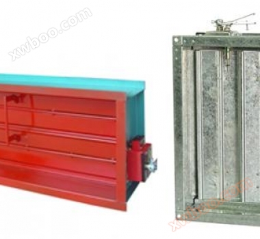
Wind valve, air outlet, fire and smoke exhaust outlet
Wind valve, air outlet, fire and smoke exhaust outlet
Product details
FoshanJiuzhou wind turbineProduct: Air Valve, Air Inlet Product Overview——
Installation instructions and precautions for fire dampers, smoke exhaust fire dampers, and smoke exhaust dampers:
1. Before installation, a comprehensive inspection should be conducted to ensure that the valve appearance is free of deformation defects, the operating mechanism is normal, and the valve action is flexible before installation.
2. When installing fire dampers and smoke exhaust fire dampers, attention should be paid to the direction of airflow, and the melting plate should be placed on the side of the ventilation port.
3. Self hanging fire dampers can be installed with horizontal airflow and vertical airflow, and attention should be paid to separate installation.
4. The valve should be reliably fixed in the designated position, and if necessary, a separate lifting bracket should be set up to ensure that its working performance is not affected by pipeline deformation during a fire.
5. When installing valves in ceilings or walls, equipment access ports should be provided with a size of not less than 450 * 450mm.
6Fire damperThe outer surface of the connecting air duct between the firewall should be insulated with refractory materials, and the electrical circuit should be protected by refractory material protective pipes.
7. When using a remote operator, the control cable should be protected by a fire-resistant pipe. The bending radius of the pipe should not be less than 250mm, and the bending point should not exceed 3 degrees. The length of the cable should not exceed 6m.
8. When the cable is wrapped around the wheel of the operator, it should not be less than 3 turns, and the cable head must be fastened with a pressure plate.
9. The shorter the cable, the better; the less bending, the better; and the larger the bending radius, the better. After installation, use a special wrench to turn the winch and tighten the cable so that the valve can be closed or opened. Then, manually and electrically adjust and check that the cable is not obstructed.
10. The DC24V start signal in the fire center has positive and negative poles, so pay attention to polarity when wiring.
11. The action feedback signal is a DC24V conditional signal, and other power sources must not be disconnected during wiring.
12. The interlocking control interface has one set of normally closed switches, which are non-contact contacts with a contact capacity of AC380V/3A.
13. For fire dampers and smoke exhaust fire dampers, the contact point is considered normal when the valve is open; For smoke exhaust valves, the contact point is considered normal when the valve is closed.


Online inquiry
-
Contacts
-
Company
-
Telephone
-
Email
-
WeChat
-
Verification Code
-
Message Content
-