
VIP member
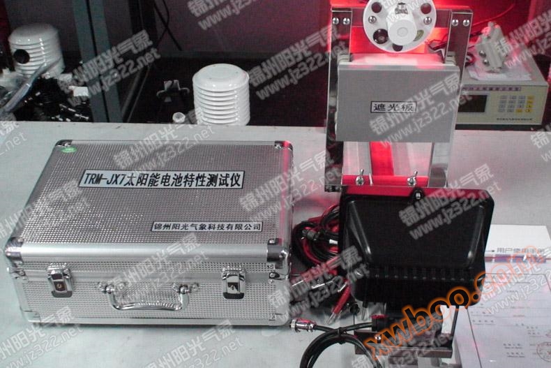
TRM-JX7 solar cell characteristic tester
This testing device uses a professional light source to simulate sunlight in the laboratory, with four solar panels installed on sliding rails. By mea
Product details
I. Overview
Solar energy is a new type of energy, and the full utilization of solar energy can solve the growing energy demand of humanity. At present, the utilization of solar energy mainly focuses on two aspects: thermal energy and photovoltaic power generation. There are currently two methods for using solar energy to generate electricity: one is to use heat energy to generate steam to drive a generator, and the other is to use solar cells. The utilization of solar energy and the study of the characteristics of solar cells are hot topics in the 21st century, and many developed countries are investing a lot of manpower and resources in researching solar receivers. This experiment introduces the electrical and optical properties of solar cells and measures both properties.

2、 Technical indicators
This testing device uses a professional light source to simulate sunlight in the laboratory, with four solar panels installed on sliding rails. By measuring light power with a solar radiometer, the volt ampere characteristics and conversion efficiency of solar cells can be measured.
Specific technical indicators:
1. Solar simulation light source: AC 220V/150W;
2. Solar cells: 4 pieces of polycrystalline silicon 60mm × 60mm × 0.3W;
3. Open circuit voltage per chip: 3.78V, short-circuit current 80mA;
4. DC stabilized power supply: continuously adjustable from 0 to 2.5V;
5. Solar radiation sensor: Test power: 0-2000W/m2 Spectral range: 320nm-1100nm Accuracy less than 5%, can be measured under simulated light source or outdoor sunlight, enabling students to better grasp solar radiation efficiency.
6. DC digital voltmeter: 0-20V, three and a half digit digital display, accuracy ± 0.5%;
7. DC digital ammeter: 0-20mA, accuracy: ± 0.5%;
8. Load resistance: 0-9999 Ω;
9. All light source brackets are made of stainless steel material, and the main body is made of aluminum and gold box structure, which is easy to carry.
3、 Experimental project
1. Voltage current characteristic testing of solar cells in the absence of light;
2. Testing the relationship between open circuit voltage, short-circuit current, and light intensity of solar cells;
3. Solar cell load characteristics and conversion efficiency testing;
4. Series and parallel experiments of solar cells;
5. Experimental method for measuring outdoor solar radiation.
4、 Experimental principle
The main structure of solar cells is PN junction. The current voltage relationship of an ideal PN junction is given by equation (1) below


When the output terminal of the solar cell is short circuited, i.e. U=0, the short-circuit current ISC=IPh can be obtained from equation (2); When the output terminal of the solar cell is open circuited, i.e. I=0, the open circuit voltage UOC can be derived. During normal operation, IPh is several orders of magnitude higher than I0, so the 1 in parentheses in equation (2) can be ignored.
When a solar cell is connected to a load resistor, the output voltage and current of the solar cell change with the variation of the load resistor. When the load resistor R is at a certain value, the output power of the solar cell is maximum, that is, the maximum output power. Let the corresponding voltage be Um and current be Im, where Pm=Im * Um. The fill factor is defined as

It is an important parameter representing the performance of solar cells. The larger the value in a certain state, the higher the utilization rate of light by the solar cell in response to the load resistance.
Online inquiry
-
Contacts
-
Company
-
Telephone
-
Email
-
WeChat
-
Verification Code
-
Message Content
-