
VIP member
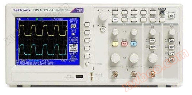
TDS1012C-SC Digital Oscilloscope
Features: TDS1001C-SCTDDS1002C-SCTS1012C-SC Display (1/4 VGALCD) Color Color Bandwidth 40MHz 60MHz 100MHz Channel Quantity 222 External Trigger Input
Product details

feature
| TDS1001C-SC | TDS1002C-SC | TDS1012C-SC | |
| Monitor (1/4 VGA LCD) | colorful | colorful | colorful |
| bandwidth | 40MHz | 60MHz | 100MHz |
| number of channels | 2 | 2 | 2 |
| External trigger input | All models include | ||
| Sampling rate for each channel | 500MS/s | 1GS/s | 1GS/s |
| Record length | All models have 2.5K points for all time bases | ||
| vertical resolution | 8 digits | ||
| vertical sensitivity | 2 mV/div -5 V/div on all models, supporting calibration and fine tuning | ||
| DC vertical accuracy | ± 3% on all models | ||
| Vertical scaling | The waveform of vertical expansion or folding activity or the waveform of stopping | ||
| Maximum input | 300 Vrms, CAT II, Rated value above 100kHz | ||
| voltage | Dropped at 20dB/10Hz, it is 13Vpk pk AC at 3MHz |
||
| Location range | 2mV-200mV/div + 2V; >200mV-5V/div+50V |
||
| Bandwidth limitation | All models are 20MHz | ||
| Input coupling | AC, DC, GND on all models | ||
| input impedance | 1M Ω parallel, 20pF | ||
| time base | 5ns-50s/div | ||
| Time base accuracy | 50ppm | ||
| Horizontal scaling | The waveform of horizontal expansion or folding activity or the waveform of stopping | ||
| I/O interface | |||
| USB port | All models include 2 USB 2.0 products The USB host product on the front panel supports USB flash drives The USB settings on the back of the instrument support connecting to PCs and all PictBridge compatible printers |
||
| GPIB | optional | ||
| Non-volatile memory | |||
| Reference waveform display | (2) 2.5K point reference waveform | ||
| Waveform storage without USB flash drive | (2) A 2.5K point | ||
| Waveform storage with USB flash drive | 96 or more reference waveforms per 8M | ||
| Waveform storage without USB flash drive | 10 front panel settings | ||
| Waveform storage with USB flash drive | More than 4000 front panel settings per 8M | ||
| Waveform storage with USB flash drive | 128 or more screen images per 8M (the number of graphics depends on the selected format) | ||
| Waveform storage with USB flash drive | Save all 12 or more operations every 8M A save all operation will save 3-9 files (Settings, images, and displaying one file for each waveform) |
||
Collection Mode
Peak detection - captures high-frequency random spikes. Capture the narrowest 12 ns (typical value) glitch using acquisition hardware on all time base settings of 5 μ s/div-50s/div.
Sampling - Only sampling data
Average - Average waveform, can choose 4, 16, 64, 128
Single Sequence - Use the Single Sequence button to capture one triggered acquisition sequence at a time
Rolling mode - on all acquisition time base settings>100ms/div
Trigger system
Trigger mode - automatic trigger, normal trigger, single sequence trigger.
Trigger Type
Edge (rising/falling edge) - traditional trigger driven by level, positive and negative slopes on any channel, coupling selection: AC, DC, noise suppression, low-frequency suppression.
Video - Trigger all lines or individual lines, synthesize odd/even fields or all fields in the video, or broadcast formats (NTSC, PAL, SECAM).
Pulse width (or modulation) - triggers a selectable time limit between 33ns and 10s that is less than, greater than, equal to, or not equal to.
trigger source
CH1, CH2, Ext, Ext/5, AC line
Trigger View
When the Trigger view button is pressed, a trigger signal is displayed
Trigger signal frequency reading
Provide frequency readings of the trigger source
cursor
Type - amplitude, time
Measurement - [Δ] T, 1 [Δ] T (frequency), [Δ]V
Automatic waveform measurement
Cycle, frequency,+width, - width, rise time, fall time, maximum value, minimum value, peak to peak value, intermediate value, cycle RMS, RMS, cursor RMS, dot space ratio, phase, delay.
Waveform mathematical operation
Operators - add, subtract, multiply, FFT
FFT window, Hanning, Flat top, rectangular, 2048 sample points.
Source - CH1, CH2, CH2-CH1, CH1+CH2, CH1 × CH2
Automatic settings menu
Single key automatic setting of vertical, horizontal, and trigger systems for all channels, with support for undo operation function
| signal type | Automatically set menu options |
| square wave | Single cycle, multi cycle, rising edge, and falling edge |
| sine wave | Single cycle, multi cycle, FFT spectrum |
| Views (NTSC, PAL, SECAM) | Field: All, odd and even Row: All rows or select row number |
Auto Range
Automatically adjust the vertical and horizontal oscilloscope settings when moving the probe point-to-point or when the signal shows significant changes
Display characteristics
Display - QVGA, Color TFT
Interpolation - Sin (x)/x
Display type - dot, vector
Afterglow - Off, 1s, 2s, 5s, infinity
Format - YT/XY
Environment and safety
Temperature - working temperature 0-50 ℃, non working temperature -40-71 ℃
Humidity - working humidity and non working humidity, 80% relative humidity at or below+40 ℃, working temperature and non working humidity: up to 45% relative humidity at maximum+50 ℃
regulatory standards
Electromagnetic compatibility capability - meets EMC Directive 2004/108/EC, EN61326 Class A standard, and meets the Australian EMC sub framework
Safety - UL61010-1:2004 CSA, C22.2 No.61010-1:2004, EN61010-1:2001, IEC61010-1:2001, EU Low Voltage Directive 2006/95EC
Physical characteristics
| Instrument appearance | |
| size | millimeter |
| wide | 326.3 |
| tall | 158.0 |
| thick | 124.2 |
| weight | kilogram |
| Only instruments | 2.0 |
| When equipped with accessories | 2.2 |
| Packaging for instrument shipment | |
| size | millimeter |
| wide | 476.2 |
| tall | 266.7 |
| thick | 228.6 |
| RM2000B rack installation | millimeter |
| wide | 482.6 |
| tall | 177.8 |
| thick | 108 |
Online inquiry
-
Contacts
-
Company
-
Telephone
-
Email
-
WeChat
-
Verification Code
-
Message Content
-