
VIP member

Product details


1.Product Introduction
KHThe series AC voltage transmitter is a measurement module that uses the principle of electromagnetic induction (mutual inductance) to convert the measured current into a DC voltage (or DC current) signal that is proportional to the primary current output. The primary and secondary sides are highly insulated. This product adopts STM technology and digital integrated circuit technology, with high overall integration, small size, and easy installation; High error accuracy, good linearity, no calibration potentiometer, able to work stably for a long time and adapt to various working environments. Widely used in the system control and detection of electrical equipment in industries such as power, petroleum, coal mining, chemical, railway, communication, and building automation.
2.FEATURES

Figure 2. Schematic diagram of AC current transmitter principle
2.1 Adopting high-precision measurement chips specifically designed for current, it has the following advantages compared to mainstream products in the industry (all of which are based on analog electrical technology):
2.1.1 Using high-precision 24 bit ∑ - △ ADC technology, the effective current error is less than 0.1% within a dynamic range of 1000:1;
2.1.2 Use software to calibrate measurement errors, without potentiometers, ensuring long-term stability and no deviation in measurement accuracy. (Currently, products in the industry are calibrated for measurement errors using potentiometers, which have large errors, poor factory consistency, and short lifespan. Especially in vibration or high-frequency electromagnetic environments, potentiometers are prone to displacement or failure, ultimately leading to transmitter failure.).
2.1.3 Built in 1.25V ± 1% reference voltage, typical temperature coefficient of 5ppm/℃, maximum 15ppm/℃. The transmitter still has ultra-high accuracy across the entire temperature range. At present, most products in the industry use analog operational amplifier technology, with a temperature coefficient of over 100 ppm/℃. The measurement linearity is poor over the entire temperature range, and the accuracy is not high. )
2.2 The use of RENESAS 16 bit MCU computer control chip has the following advantages compared to mainstream products in the industry (none of which have MCU):
2.2.1 Digitize the measurement results, reduce noise interference, and enhance the anti-interference ability of the product.
2.2.2 The factory parameters of the product are configured using software, and the product has no short contacts or potentiometers. The product is reliable and has a long lifespan.
2.2.3 It has a pulse indicator light output function that is proportional to the measured current value. It is red, usually off, and flashes when measuring current value. Convenient for on-site installation and debugging.
2.2.4 Equipped with a transmitter working status indicator light, green, lit when there is no measured current; When there is current, turn off.
2.2.5 Equipped with RS485 communication interface (optional), capable of reading the measured current value.
2.2.6 It has the function of alarm output for current exceeding the upper or lower limit (optional).
2.3 Adopting TI's current loop output chip has the following advantages compared to mainstream products in the industry (discrete circuits):
2.3.1 Nonlinear error: 0.002%;
2.3.2 Low temperature drift: 1 µ V/℃;
2.3.3 Accuracy: 0.015%;
2.3.3 Wide working voltage range of 7-36V.
2.4 Adopt SMT welding process.
2.5 All use well-known brand components with industrial grade standards, and the products are designed according to industrial grade standards.
2.6 Multiple circuit protection functions ensure reliable operation of the transmitter in various environments.
2.6.1 Reverse protection for working power supply connection;
2.6.2 Output overcurrent limit protection;
2.6.3 RS485 abnormal access protection;
2.6.4 Transient induction lightning and surge current TVS suppression protection for current/voltage output ports;
2.6.5 Built in voltage filtering circuit, with low requirements for input power ripple.

4.electrical parameter
| Ib | Rated current value(Arms) | 10 20 50 100 200 300 400 500 600 800 1000 |
| Imax | Maximum current value (Arms) | 120% * Ib |
| Ioc | Overload capacity | 200% * Ib |
| Vsn(Corresponding to voltage output type) | Output voltage (Vdc) | DC0-5V, DC0-10V etc |
| Isn(Corresponding to current output type) | Output current (mAdc) | DC4-20mA,DC0-20mA etc |
| X | Accuracy (Ta=+25 ℃) | 0.5% |
| EL | Linearity Error | 0.2% |
| Vc | supply voltage | DC8-30V |
| Tr | reaction time | ≤ 300mS |
| f | Frequency range | 40-200HZ |
| Ic | consume power | ≤ 0.8W |
| RL | load resistance | ≥ 5k Ω (voltage output type) |
| ≤ 500 Ω (current output type) | ||
| Ioutmax | maximum output current | Typ ≤25 mA |
| Vd | Power frequency withstand voltage (50HZ, 1min) | 5KV |
| Ri | insulation resistance | Greater than 20M Ω @ DC500V |
| imp/mAh | Current pulse constant output | 30000 imp/mAh (unique innovative feature) |
5.General parameters:
| Ta | operation temperature | -40 - +80 ℃(Superior to other manufacturers)-10- +70 ℃) |
| Ts | Storage temperature | -55 - +85 ℃ |
| W | weight | About 250g |
| St | Execution standards | GB/T13850-1998/IEC688:1992 |
| Hw | Working humidity | 20-90% no condensation |
6. Connection
KTB8-A wiring terminal
Terminal 7 (OUT -): Output 4-20mA negative pole
Terminal 9 (OUT+): Output 4-20mA positive pole
Terminal 10 (P -): Negative pole of power supply DC24
Terminal 12 (P+): Positive pole of power supply DC24
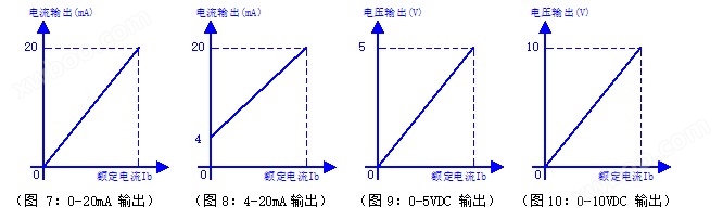
7.Output curve
Online inquiry
-
Contacts
-
Company
-
Telephone
-
Email
-
WeChat
-
Verification Code
-
Message Content
-