
VIP member
MGS-2443-H16R Magnetic Guidance Sensor
MGS-2443-H16R Magnetic Guidance Sensor
Product details
1: Overview:
Our company's self-developed MGS-2443-H16R is a magnetic guidance sensor (also known as a magnetic navigation sensor) used for magnetic track guided unmanned driving AGV vehicles. MGS-2443-H16R is an extended version of our company's directional sensor, which adds RS-485 serial signal transmission on the basis of MGS-2473-H16 (16 bit switch signal parallel output). The serial interface uses imported high-speed optocouplers for electrical isolation, and the sensor can communicate with PC or PLC at a high speed. The sensor is made of imported high-sensitivity magnetic sensors and large-scale integrated logic processing circuits, which have better sensitivity. As long as the magnetic field at the detection surface of the sensor is higher than 6GS, offset detection can be carried out; Internally equipped with short-circuit protection and overvoltage protection. Fast communication response time, stable and reliable performance.
The sensor is installed on the unmanned AGV car, with a distance of 5-30mm between the sensor and the guiding magnetic strip. During the operation of the car, if the car deviates from the track, one or more of the 16 bit switches built into the sensor will change their status. The system will issue various commands based on the combination code of the sensor switch status, so that the car can travel along the track correctly; The 16 bit switches are all output in an NPN collector open circuit manner, and users can use a certain switch to control loads with operating currents less than 100 milliamps as needed.
2: Main parameters of MGS-2443-H16R magnetic navigation sensor:
project |
parameter |
Remarks |
Specification |
MGS-H-S-20-C20-N-R |
|
Product Code |
MGS-2443-H16R |
|
Main material |
aluminum alloy |
|
power supply voltage |
9-24VDC |
|
load current |
100m A ( max) |
|
output channel |
Route 16 |
|
output type |
discrete signal |
|
sensing distance |
5-30mm |
|
Measurement offset range |
±100mm |
|
output method |
NPN collector open circuit output |
|
signal amplitude |
VOL≤0.6V |
VCC=12V |
VOH≥11V | ||
Protection type |
Short circuit protection, polarity protection |
|
insulation resistance |
50MΩ (min) |
|
electrical connection |
20PIN Jianniu connector |
The parallel signal output interface complies with MIL-C-83503 standard socket |
8PIN with flange socket |
RS-485 communication interface |
|
response time |
parallel signal |
1ms MAX |
serial signal |
8ms @ 19200 (related to baud rate) |
|
tensile strength |
5kg |
Between socket and shell |
service life |
3 years |
|
ambient temperature |
-25—75℃ |
|
humidity |
90% max |
|
mechanical vibration |
7g |
F=20-400Hz, in each direction |
mechanical shock |
10g/16ms |
1000 times, in each direction |
Protection level |
IP65 |
|
esd protection |
4.5KV |
|
Electric field interference |
200V/m |
|
Installation and Usage |
Adapt to magnetic stripe N-pole |
50 × 1.2, field strength not less than 10Gs at a height of 40mm from the centerline of the magnetic stripe |
Installation direction |
Align the centerline of the sensor with the centerline of the magnetic stripe |
|
Application field |
Automated Guided Vehicle (AGV) |
|
Trackless mobile shelves, logistics picking and other industries |
||
Automatic Handcart AGC |
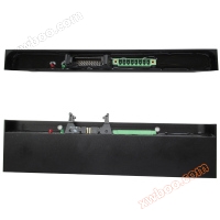
3: External dimensions

4: Pin attributes
1: 20PIN Jianniu connector
pin number |
attribute |
pin number |
attribute |
pin number |
attribute |
1 |
Switching output1 |
8 |
Switching output8 |
15 |
Switching output15 |
2 |
Switching output2 |
9 |
Switching output9 |
16 |
Switching output16 |
3 |
Switching output3 |
10 |
Switching output10 |
17 |
negative terminal of power supply |
4 |
Switching output4 |
11 |
Switching output11 |
18 |
|
5 |
Switching output5 |
12 |
Switching output12 |
19 |
|
6 |
Switching output6 |
13 |
Switching output13 |
20 |
positive power terminal |
7 |
Switching output7 |
14 |
Switching output14 |
2: 8PIN with flange connector
pin number |
attribute |
pin number |
attribute |
1 (V+) 等同简牛PIN20 |
positive power terminal |
5 (+5V OUT) |
Sensor+5V output |
2 (V-) 等同简牛PIN19 |
negative terminal of power supply |
6 (+5V IN) |
External+5V input |
3 (SEL) |
Address Selection |
7 A |
485 A |
4 |
Manufacturer reserves |
8 B |
485 B |
5: Wiring diagram
1: Parallel signal interface:

2Serial signal interface

Note:
(1) The negative terminal of PIN 2 power supply is short circuited to the output ground of the controller, which means that the sensor and controller must be grounded together.
(2) When the PIN 3 address selection pin is short circuited to ground, the sensor address is forced to be 1 (0X01), the baud rate is 19200 (code 0x02), and when it is open circuited, the address is the address code written by the customer to register 0 using a write operation. The baud rate is the baud rate corresponding to the code written into register 1.
(3) Pin 6 external+5V input is connected to the+5V output of the controller to electrically isolate the sensor from the controller; If the controller cannot provide a+5V power supply, the pin can be short circuited to PIN 5 and the internal+5V power supply of the sensor can be used.
6: RS-485 communication protocol:
(one)Word format:
Baud rate9600、14400、19200、28800、38400、57600.
Word format definition:
Starting position:1
Data bit:8
Checkpoint: None
Stop position:1
The forced address of the sensor is0x01Cannot be modified, the initial address is0x02, saved at the address0The register can be modified by write operations.
Sensors only involve2A function code(0x03Read the sensor output signal;0x06Write the local address or set the baud rate.)
(two)The frame format is as follows: (The registers used by the sensor are all single byte registers)
1:Read sensor output signal: PleasePIN3Grounding, to19200Send read operation instructions to the sensor at the baud rate.
A:Host message
. Byte |
Second byte |
Third byte |
Fourth byte |
CRC16verify(8005) |
|
address code |
function code |
register address |
number of registers |
low8bit |
tall8 bit |
01 |
03 |
00 |
02 |
70 |
19 |
Message meaning: To address:1 The sensor sends a command to transmit the current sensor signal from the register0Start, read continuously2 The value of a register; A total of two bytes of data. The last two bytes are the checksum calculated by the host, and the sensor recalculates the first four bytes received and checks them against the checksum.
If the verification code matches, send a message back to the host; otherwise, continue waiting for the command.
B:Sensor return message
. Byte |
Second byte |
Third byte |
Fourth byte |
CRC16verify(8005) |
|
address code |
function code |
register0value |
register1value |
low8bit |
tall8 bit |
01 |
03 |
00 |
FF |
B1 |
98 |
Message meaning: The sensor receives a valid command; Calculate the checksum by combining the local address, function code, and two bytes of data, and attach it to the front4 Send to host after byte: the third byte is inside the sensor1-8Position switch status, the fourth byte is inside the sensor9-16Position switch status, with the fifth and sixth bytes as verification codes. According to the data, the sensor currently only has the fifth and sixth bytes1-8Placed in the magnetic field0Other positions were set without detecting a magnetic field1.
2:Write the local address: Please provide itPIN3Grounding, to19200Send write operation instructions to the sensor at the baud rate.
A:Host message
. Byte |
Second byte |
Third byte |
Fourth byte |
CRC16verify(8005) |
|
address code |
function code |
register address |
number of registers |
low8bit |
tall8 bit |
01 |
06 |
00 |
02 |
60 |
18 |
Message meaning: The host needs to modify the sensor address to0x02, and save it to the hold register0In the middle.
B:Sensor return message
. Byte |
Second byte |
Third byte |
Fourth byte |
CRC16verify(8005) |
|
address code |
function code |
register address |
number of registers |
low8bit |
tall8 bit |
01 |
06 |
00 |
02 |
60 |
18 |
Message meaning: The sensor has modified the local address to0x02, and save it to the hold register0In the middle. atPIN3Open circuit to ground and reset sensor(power on again)Afterwards, the local address is0x02;
3:Set baud rate: PleasePIN3Grounding, to19200Send write operation instructions to the sensor at the baud rate.
A:Host message
. Byte |
Second byte |
Third byte |
Fourth byte |
CRC16verify(8005) |
|
address code |
function code |
register address |
number of registers |
low8bit |
tall8 bit |
01 |
06 |
01 |
06 |
60 |
4B |
Message meaning: The host needs to modify the baud rate code of the sensor to0x06 (Corresponding baud rate115200), and save it to the hold register1In the middle.
B:Sensor return message
. Byte |
Second byte |
Third byte |
Fourth byte |
CRC16verify(8005) |
|
address code |
function code |
register address |
number of registers |
low8bit |
tall8 bit |
01 |
06 |
01 |
06 |
60 |
4B |
Message meaning: The sensor has modified the baud rate code to0x06, and save it to the hold register1In the middle. atPIN3Open circuit to ground and reset sensor(power on again)Afterwards, this machine57600Communicate at a baud rate.
Appendix: Comparison Table of Baud Rate Codes, Corresponding Baud Rates, and Sensor Response Times
code |
0 |
1 |
2 |
3 |
4 |
5 |
Baud rate |
9600 |
14400 |
19200 |
28800 |
38400 |
57600 |
response timems |
20 |
11 |
8 |
6 |
4.5 |
3 |
7: Precautions for use:
1: Please use a 9-24V DC stabilized power supply to power the sensor, avoiding high-power inductive and capacitive loads such as sensors and motors sharing the power supply
2: Pay attention to the pin properties and avoid misconnecting. It is strictly prohibited to connect the output pin to the positive or negative pole of the power supply.
3: The manufacturer reserves the terminals and strictly prohibits any connection, otherwise it may cause damage to the sensor invalid.
4: When installing the sensor, try to keep it as far away from the motor as possible, leaving at least 80mm gap, to avoid sensor misoperation caused by the magnetic field generated by the motor winding.
5: If you want to use an RS-485 converter, please use an industrial grade active isolation converter and not a commercial grade passive converter.
6: In long-distance signal transmission, in order to avoid signal reflection and echo, it is generally necessary to connect the two terminals of the cable to the terminal
Resistance capacitance absorption. The terminal matching resistance value depends on the impedance characteristics of the cable and is independent of the length of the cable.RS-485Generally adopted
Connect with twisted pair cables (shielded or unshielded), and the terminal resistance is generally between100 to140Between Ω, the typical value is120Oh?
Capacitors are usually used0.1uF(104)In actual configuration,PLCorPCThe upper computer is connected to one end of the cable
On two terminal nodes, namely Near end and Remote, each connected to a terminal for impedance and capacitance absorption, while the nodes in the middle are
Cannot connect impedance capacitance absorption, otherwise it will cause communication errors.

8: Ordering information:
serial number |
main model |
型谱 |
Feature Description |
|||||
5 |
MGS |
—□ |
—□ |
—□ |
- □ |
—□ |
—□ |
Indicating a magnetic track navigation sensor |
Magnetic navigation sensor |
H |
Hall rffect |
||||||
R |
Switches (switch type) |
|||||||
V |
voltage output |
|||||||
I |
current output |
|||||||
P |
pulse output |
|||||||
S |
switch output |
|||||||
—□ |
Response distance (mm), represented by numbers |
|||||||
—□ |
Lead out length |
|||||||
—□ |
The number of connector pins is represented by a C+number |
|||||||
N |
Detecting magnetic pole as N pole |
|||||||
S |
Detecting magnetic pole as S pole |
|||||||
empty |
Only parallel signal output |
|||||||
R |
Parallel signal+RS485 output |
|||||||
Online inquiry
-
Contacts
-
Company
-
Telephone
-
Email
-
WeChat
-
Verification Code
-
Message Content
-