
VIP member
JYF wing type wind measurement device
JYF wing type wind measurement device
Product details
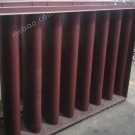
This device consists of a wing installed in the air duct, a differential pressure measuring tube, and a section of air duct. The line shape of the wing is divided into four sections on each side, with three sections being arc-shaped plates with different curvature radii, and the fourth section being a straight plate.
According to the principles of fluid mechanics, when the airflow in the air duct passes through the wing measuring device (see Figure 1), it generates a flow around the wing surface and creates a pressure difference between stagnation point A and chord point B (B '). The pressure at stagnation point A is full pressure, while the pressure at chord point B (B') decreases due to the contraction of the flow cross-section at that point, resulting in a decrease in static pressure. Therefore, the pressure difference between A and B (B ') is proportional to the airflow velocity V or flow rate Q. By measuring the differential pressure, the flow rate can be measured.
Online inquiry
-
Contacts
-
Company
-
Telephone
-
Email
-
WeChat
-
Verification Code
-
Message Content
-