
VIP member

IS horizontal single-stage single suction centrifugal pump
IS horizontal single-stage single suction centrifugal pump, suitable for industrial and urban water supply and drainage, and can also be used for agri
Product details
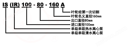
Model Meaning
Product Introduction
IS single-stage single suction centrifugal pump is suitable for industrial and urban water supply and drainage, and can also be used for agricultural irrigation and drainage. Used for transporting clean water or other liquids with physical and chemical properties similar to clean water, with a temperature not exceeding 80 ℃.
Performance range of the pump (based on design points):
Rotational speed: 2900r/min and 1450r/min
Imported diameter: 50-200mm
Flow rate: 6.3-400 m3/h
Lift: 5-125
Product Usage
1. Suitable for urban environmental protection, construction, fire protection, chemical, pharmaceutical, dye, printing and dyeing, brewing, electricity, electroplating, papermaking, petroleum, mining, equipment cooling, oil tanker unloading, etc.
2. Suitable for clear water, seawater, chemical media liquids with acid and alkalinity, and slurries with general paste like properties (medium viscosity ≤ 100 cP, solid content up to 30% or less).
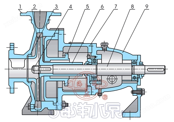
structural diagram
 |
serial number |
name |
serial number |
name |
1 |
pump body |
6 |
intermediate support |
|
2 |
impeller |
7 |
axis
|
|
3 |
sealing ring |
8 |
Suspension components |
|
4 |
impeller nut |
9 |
Sealing member |
|
5 |
pump cover |
performance parameters
|
model
|
Traffic Q
|
Head H
|
Speed n
|
Motor power
|
|
|
m3/h
|
L/s |
m |
r/min |
kW |
|
IS50-32-125 |
12.5 |
3.47 |
20 |
2900 |
2.2 |
IS50-32-160 |
12.5 |
3.47 |
32 |
2900 |
3 |
IS50-32-200 |
12.5 |
3.47 |
50 |
2900 |
5.5 |
IS50-32-250 |
12.5 |
3.47 |
80 |
2900 |
11 |
IS65-50-125 |
25 |
6.94 |
20 |
2900 |
3 |
IS65-50-160 |
25 |
6.94 |
32 |
2900 |
5.5 |
IS65-40-200 |
25 |
6.94 |
50 |
2900 |
7.5 |
IS65-40-250 |
25 |
6.94 |
80 |
2900 |
15 |
IS65-40-315 |
25 |
6.94 |
125 |
2900 |
30 |
IS80-65-125 |
50 |
13.9 |
20 |
2900 |
5.5 |
IS80-65-160 |
50 |
13.9 |
32 |
2900 |
7.5 |
IS80-50-200 |
50 |
13.9 |
50 |
2900 |
15 |
IS80-50-250 |
50 |
13.9 |
80 |
2900 |
22 |
IS80-50-315 |
50 |
13.9 |
125 |
2900 |
37 |
IS100-80-125 |
100 |
27.8 |
20 |
2900 |
11 |
IS100-80-160 |
100 |
27.8 |
32 |
2900 |
15 |
IS100-65-200 |
100 |
27.8 |
50 |
2900 |
22 |
IS100-65-250 |
100 |
27.8 |
80 |
2900 |
37 |
IS100-65-315 |
100 |
27.8 |
125 |
2900 |
75 |
IS125-100-200 |
200 |
55.5 |
50 |
2900 |
45 |
IS125-100-250 |
200 |
55.6 |
80 |
2900 |
75 |
IS125-100-315 |
200 |
55.6 |
125 |
2900 |
90 |
model |
Traffic Q |
Head H |
Speed n |
Motor power |
|
m3/h |
L/s |
m |
r/min |
kW |
|
IS50-32-125 |
6.3 |
1.74 |
5 |
1450 |
0.55 |
IS50-32-160 |
6.3 |
1.74 |
8 |
1450 |
0.55 |
IS50-32-200 |
6.3 |
1.74 |
12.5 |
1450 |
0.75 |
IS50-32-250 |
6.3 |
1.74 |
20 |
1450 |
1.5 |
IS65-50-125 |
12.5 |
3.74 |
5 |
1450 |
0.55 |
IS65-50-160 |
12.5 |
3.47 |
8 |
1450 |
0.75 |
IS65-40-200 |
12.5 |
3.74 |
12.5 |
1450 |
1.1 |
IS65-40-250 |
12.5 |
3.74 |
20 |
1450 |
2.2 |
IS65-40-315 |
12.5 |
3.74 |
32 |
1450 |
4 |
IS80-65-125 |
25 |
6.94 |
5 |
1450 |
0.75 |
IS80-65-160 |
25 |
6.94 |
8 |
1450 |
1.5 |
IS80-50-200 |
25 |
6.94 |
12.5 |
1450 |
2.2 |
IS80-50-250 |
25 |
6.94 |
20 |
1450 |
3 |
IS80-50-315 |
25 |
6.94 |
32 |
1450 |
5.5 |
IS100-80-125 |
50 |
13.9 |
5 |
1450 |
1.5 |
IS100-80-160 |
50 |
13.9 |
8.0 |
1450 |
2.2 |
IS100-65-200 |
50 |
13.9 |
12.5 |
1450 |
4 |
IS100-65-250 |
50 |
13.9 |
20 |
1450 |
5.5 |
IS100-65-315 |
50 |
13.9 |
32 |
1450 |
11 |
IS125-100-200 |
100 |
27.8 |
12.5 |
1450 |
7.5 |
IS125-100-250 |
100 |
27.8 |
20 |
1450 |
11 |
IS125-100-315 |
100 |
27.8 |
32 |
1450 |
15 |
IS125-100-400 |
100 |
27.8 |
50 |
1450 |
30 |
IS150-125-250 |
200 |
55.6 |
20 |
1450 |
18.5 |
IS150-125-315 |
200 |
55.6 |
32 |
1450 |
30 |
IS150-125-400 |
200 |
55.6 |
50 |
1450 |
40 |
IS200-150-250 |
400 |
111.1 |
20 |
1450 |
37 |
IS200-150-315 |
400 |
111.1 |
32 |
1450 |
55 |
IS200-150-400 |
400 |
111.1 |
50 |
1450 |
90 |
Assembly and disassembly
The assembly and disassembly of IS single-stage single suction centrifugal pump: Before assembly, the parts should be checked for any defects that may affect the assembly and cleaned thoroughly before proceeding with the assembly.
1. Pre tighten the connecting bolts, plugs, etc. at each location onto the corresponding parts.
2. You can place O-ring seals, paper pads, felt, etc. on the corresponding parts in advance.
3. The sealing ring and packing, packing ring, packing cover, etc. can be installed into the pump cover in sequence.
4. Install the rolling bearing onto the shaft, then install it into the suspension, close the cover, tighten the rolling bearing, and fit the connecting bolt onto the shaft.
5. Install the shaft onto the shaft, then install the pump cover onto the suspension, and finally install and tighten the impeller, stop washer, impeller nut, etc. Install the above components into the pump body and tighten the connecting bolts on the pump body and pump cover.
During the above assembly process, some small parts such as flat keys, oil deflectors, O-ring seals inside the water deflector sleeve, etc. are prone to omission or installation in the wrong order, and special attention should be paid.
The disassembly sequence of IS single-stage single suction centrifugal pump can be basically carried out in the reverse of the assembly sequence.
install
The installation of IS single-stage single suction centrifugal pump has a significant impact on the operation and service life of the pump, so installation and calibration must be carried out carefully. The appearance and installation dimensions of the pump.
1Installation and calibration:
(1) Remove the grease and dirt from the base and place it on the foundation.
(2) Check the levelness of the base with a spirit level and allow for leveling with a wedge iron.
(3) Pour cement into the base and anchor bolt holes.
(4) After the cement has dried and solidified, the base and anchor bolt holes should be checked for looseness. If they are suitable, the anchor bolts should be tightened and the levelness checked again.
(5) Clean the support plane of the base, the plane of the water pump foot and motor foot, and install the water pump and motor onto the base.
(6) A certain gap should be maintained between the couplings, and the centerline of the water pump shaft and motor shaft should be checked for consistency. Thin gaskets can be used to adjust them to be concentric.
The difference between the upper and lower outer circles of the coupling should not exceed 0.1 mm, and the difference in the gap between the end faces of the two couplings should not exceed 0.3 mm.
2Installation instructions:
(1) The installation height of the pump, the length, diameter, and flow rate of the pipeline should comply with the calculation, striving to reduce unnecessary losses.
(2) When transporting over long distances, a larger pipe diameter should be used, and the pump pipeline should have its own support. The weight of the pipeline should not be added to the pump to avoid damaging it.
(3) If a check valve is installed in the discharge pipeline, it should be installed outside the gate valve.
Starting, stopping, and running
1start:
(1) Before connecting the pump, it should be determined whether the rotation direction of the motor is correct and whether the pump operates flexibly.
(2) Close the gate valve on the discharge pipeline.
(3) Fill the pump with water or use a vacuum pump to draw water.
(4) Connect the power supply, gradually open the gate valve on the discharge pipeline when the pump reaches normal speed, and adjust it to the required working condition. With the gate valve on the discharge pipeline closed, the pump should not work continuously for more than 3 minutes.
2停止:
(1) Gradually close the gate valve on the discharge pipeline and cut off the power supply.
(2) If the ambient temperature is below O ℃, the water in the pump should be drained to prevent freezing and cracking.
(3) If the pump is not used for a long time, it should be disassembled, cleaned, oiled, packaged and stored.
3work:
(1) During driving and operation, it is necessary to pay attention to observing the instrument readings, bearing heating, packing leakage and heating, and whether the vibration and noise are normal. If any abnormal situations are found, they should be dealt with immediately.
(2) The bearing temperature shall not exceed 80 ℃, and the bearing temperature shall not exceed 40 ℃ higher than the ambient temperature.
(3) The filling is normal, and the leakage should be small and uniform.
(4) The bearing oil level should be kept at the normal position, not too high or too low, and lubricating oil should be replenished in a timely manner when it is too low.
(5) If the clearance wear between the sealing ring and the impeller is too large, a new sealing ring should be replaced.
Reference Table for Pipeline Losses
Pipe diameter mm |
Flow rate (L/S) |
|||||||||||||||||||||||
1 |
2 |
4 |
6 |
8 |
10 |
|||||||||||||||||||
25 |
3.2 |
13 |
||||||||||||||||||||||
38 |
3.5 |
14 |
15 |
15 |
20 |
|||||||||||||||||||
50 |
0.8 |
3.1 |
13 |
29 |
25 |
30 |
||||||||||||||||||
65 |
0.8 |
3.2 |
7.1 |
13 |
20 |
40 |
50 |
|||||||||||||||||
75 |
0.4 |
1.6 |
3.3 |
5.9 |
9.6 |
21.6 |
60 |
70 |
||||||||||||||||
100 |
0.4 |
0.8 |
1.3 |
2.1 |
6.8 |
8.6 |
13 |
19. |
80 |
90 |
||||||||||||||
125 |
0.2 |
0.4 |
0.6 |
1.3 |
2.7 |
4.1 |
5.9 |
10. |
100 |
110 |
||||||||||||||
150 |
0.1 |
0.2 |
0.5 |
1.1 |
1.6 |
2.3 |
4.2 |
6.4 |
9.4 |
120 |
130 |
|||||||||||||
175 |
0.1 |
0.2 |
0.5 |
0.7 |
1.0 |
1.9 |
2.9 |
4.3 |
5.8 |
7.7 |
9.6 |
140 |
160 |
|||||||||||
200 |
0.1 |
0.2 |
0.3 |
0.5 |
0.9 |
1.5 |
2.1 |
2.9 |
3.7 |
4.7 |
6.1 |
7.2 |
8.5 |
180 |
200 |
|||||||||
250 |
0.1 |
0.1 |
0.2 |
0.3 |
0.5 |
0.7 |
0.9 |
1.2 |
1.5 |
1.9 |
2.3 |
2.8 |
3.3 |
3.7 |
4.9 |
5.2 |
||||||||
300 |
0.1 |
0.1 |
0.2 |
0.3 |
0.4 |
0.5 |
0.6 |
0.7 |
0.9 |
1.1 |
1.3 |
1.5 |
2.0 |
2.4 |
3.0 |
|||||||||
Valve and bent pipe converted to straight pipe length
category |
Equivalent to multiple of straight pipe diameter |
Remarks |
Fully open gate valve |
12 |
Unopened double |
normal bend |
25 |
|
check valve |
100 |
|
foot valve |
100 |
Partial blockage doubles |
The flow limit of a certain pipeline is certain
|
|
Common causes and solutions of malfunctions
fault |
reason |
solution |
1. The water pump is not absorbing water, and the pointers of the pressure gauge and vacuum gauge are swinging violently. |
The water injected into the pump is not enough, and there is a leak in the water pipe or instrument. |
Inject or twist into the water pump again: tighten and block the leak. |
|
2. The water pump does not absorb water, and the vacuum gauge indicates high vacuum.
|
The low valve has not been opened, or the suction pipe has been clogged with too much resistance, and the suction pipe is too high.
|
Correct or modify the bottom valve. Clean or modify the pump water pipe to reduce the suction height.
|
3. According to the pressure gauge, there is pressure at the outlet of the water pump, but the water pipe still does not discharge water. |
The resistance of the outlet pipe is too high, the rotation direction is incorrect, and the impeller is clogged. |
Check or shorten the water pipe and remove the water pipe joint from the motor, and clean the impeller.
|
4. The traffic is lower than expected. |
The water pump is clogged and the mouth ring is worn out too much. |
Clean the water pump and pipes, and replace the mouth ring. |
5. The power consumption of the water pump is too high. |
The stuffing box is compressed too tightly, causing it to heat up. Due to wear and tear, the impeller is damaged, resulting in an increase in the water supply of the pump. |
Tighten the packing box, or take out the packing and make it square, replace the impeller, increase the resistance of the outlet pipe to reduce the flow rate. |
|
6. The internal sound of the water pump is abnormal, and the water pump is not functioning properly.
|
The flow rate is too high, the resistance inside the suction pipe is too high, the suction height is too high, air infiltrates at the suction point, and the temperature of the transported liquid is too high. |
Increase the resistance in the outlet pipe to reduce the flow rate, check the resistance in the pump suction pipe, and check the bottom valve to reduce the suction height. Tighten and block the leak to reduce the liquid temperature. |
7. The bearing is overheated. |
Without oil, the water pump shaft and motor shaft are not on the same centerline.
|
Inject oil and align the center of the shaft. |
8. Pump vibration. |
The pump shaft and motor shaft are not on the same centerline or the pump shaft is skewed.
|
Align the axis centerlines of the water pump and motor. |
Online inquiry
-
Contacts
-
Company
-
Telephone
-
Email
-
WeChat
-
Verification Code
-
Message Content
-