
VIP member
Forged steel gate valves Z61Y~Z11Y
Forged steel gate valves Z61Y~Z11Y
Product details
Shanghai Wilton Valve Co., LtdMain production(Forged steel gate valves Z61Y~Z11Y)Also domestically(Gate valve)One of the producers. Business scope of the company: production, processing, and sales of valves, fittings, and fluid equipment, sales of pipeline fittings, building materials, hardware and electrical equipment, and automatic control equipment, engaged in import and export business of goods and technology! Welcome new and old customers to call or write to us. We will wholeheartedly provide you with satisfactory service!
Forged Steel Gate Valves Z61Y~Z11Y Product Overview:
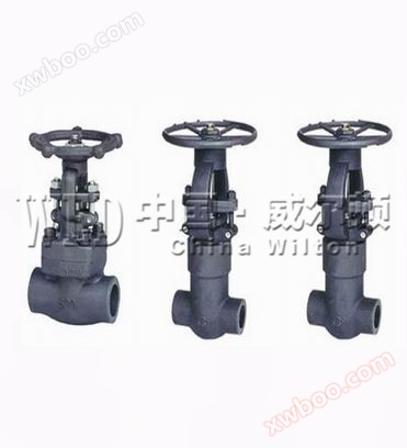
Forged steel gate valveZ61Y~Z11YThere are three types of valve cover designs. The first type is bolt type valve cover. Valves designed in this form have their valve body and cover connected by bolts and nuts, and wrapped gaskets(316Clamp flexible graphite manufacturing) seal. When customers have special requirements, metal rings can also be used for connection. The second design form is a welded valve cover. According to this design form, the valve body and valve cover are connected by threads and fully welded sealed. When customers have special requirements, full penetration welding can also be used. The third type is the pressure self tightening valve cover. Valves designed in this form have a threaded connection between the valve body and the valve cover, and are sealed with an internal pressure self sealing ring.
Application scope:
Forged steel gate valve is suitable forClass150~Class2500Working temperature-29℃~425℃(Carbon steel) or-29℃~500℃On small-diameter pipelines made of stainless steel, it is used to cut off or connect media in the pipeline. Different materials are selected and can be applied to various media such as water, steam, oil, nitric acid, acetic acid, oxidizing media, urea, etc.
Structural features:
1Forged steel gate valves have low fluid resistance, and their resistance coefficient is equal to that of pipe sections of the same length.
2The product structure of forged steel gate valve is simple, small in size, and light in weight.
3Tight and reliable, currently gate valves have good sealing performance and have been widely used in vacuum systems.
4Easy maintenance, simple gate valve structure, and easy disassembly and replacement.
Forged steel gate valves often overlook pressure issues. During the grease injection operation, the pressure of the semi free floating ball steam trap varies rhythmically with peaks and valleys. Low pressure, seal leakage or safety valve failure,Excessive pressure may cause blockage of the grease injection valve manufacturer, hardening of the grease inside the seal, or locking of the sealing ring with the valve ball or valve plate. When the grease injection pressure is usually too low, the injected lubricating grease tends to flow into the bottom of the valve chamber, usually occurring in small gate valves. If the pressure of the grease injection flow control valve is too high, on the one hand, check the insulation gate valve and grease injection nozzle. If it refers to the blockage of the remote control float valve hole, determine the situation and replace it with a spring seal with a wrench fully open condition; On the one hand, the plunger globe valve is hardened with grease, which requires the use of cleaning solution to repeatedly soften the failed sealing grease and inject new lubricating grease for replacement. In addition, the sealing model and sealing material also affect the grease injection pressure. Different sealing forms have different grease injection pressures, and in general, the grease injection pressure of hard seal gate valves is higher than that of soft seal gate valves.
Standard specifications:
Design and Manufacturing Standards:JB/T 7746TheAPI602
Structural length standard:GB/T 12221-2005
Connection flange standard:GB/T 9113
Socket welding standard:JB/T 1751TheASME B16.11
Threaded connection standard:GB 7306TheASME B2.1
Pressure and temperature rating:GB/T 12224-2005
Test and inspection standards:GB/T 13927-2008
Part materials and working conditions:
|
serial number |
Part Name |
CS to ASTMcarbon steel |
AS to ASTMalloy steel |
SS to ASTMstainless steel |
|
|
A105 |
F22 |
F304(L) |
F316(L) |
||
|
1 |
valve body |
A105 |
A182F22 |
A182F304(L) |
A182F316(L) |
|
2 |
valve seat |
A276420 |
A276304 |
A276304(L) |
A276316(L) |
|
3 |
ram |
A182F430&410 |
A182F304 |
A182F304(L) |
A182F316(L) |
|
4 |
valve stem |
A182F6 |
A182F304 |
A182F304(L) |
A182F316(L) |
|
5 |
shim |
316Clamp flexible graphite |
316clipPTFE |
||
|
6 |
valve cover |
A105 |
A182F22 |
A182F304(L) |
A182F316(L) |
|
7 |
bolt |
A193B7 |
A193B16 |
A193B8 |
A193B8M |
|
8 |
dowel pin |
A276420 |
A182F304 |
||
|
9 |
packing gland |
A276410 |
A182F304(L) |
A182F316(L) |
|
|
10 |
swivel bolt |
A193B7 |
A193B16 |
A193B8 |
A193B8M |
|
11 |
packing gland |
A105 |
A182F11 |
A182F304(L) |
A182F316(L) |
|
12 |
nut |
A1942H |
A1944 |
A1948 |
A1948M |
|
13 |
stem nut |
A276420 |
|||
|
14 |
lock nut |
A1942H |
A1944 |
A1948 |
A1948M |
|
15 |
nameplate |
SS |
|||
|
16 |
handwheel |
A197 |
|||
|
17 |
shim |
A473431 |
|||
|
18 |
filler |
flexible graphite |
PTFE |
||
|
Applicable Medium |
Water, steam, oil products, etc |
Water, steam, oil products, etc |
Nitric acid, acetic acid, etc |
||
|
Applicable Temperature |
—29℃~425℃ |
—29℃~550℃ |
—29℃~200℃ |
||
Attention: Other materials required by the customer can also be used, and the sealing surface material is determined by matching the customer's specified internal part code.
Main dimensions and weight:
|
NPS |
Shrinking diameter |
3/8' |
1/2' |
3/4' |
1' |
11/4' |
11/2' |
2' |
|
|
Full diameter |
|
3/8' |
1/2' |
3/4' |
1' |
11/4' |
11/2' |
2' |
|
|
L |
92 |
111 |
111 |
120 |
120 |
140 |
178 |
210 |
|
|
H(open) |
169 |
197 |
197 |
236 |
246 |
283 |
330 |
354 |
|
|
W |
100 |
125 |
125 |
160 |
160 |
180 |
200 |
240 |
|
|
weight |
Bolt type |
2.5 |
4.3 |
4.2 |
6.6 |
8.8 |
12.5 |
17.2 |
23.5 |
|
welded type |
2.4 |
4.2 |
4.0 |
6.3 |
8.7 |
12.1 |
17.2 |
22.0 |
|
Structural diagram of forged steel gate valves Z61Y~Z11Y:

Ordering process:
1. Fax the customer's purchase list, call for consultation, or email shweierdun@163.com
2. Received the customer's purchase list and provided the customer with valve model selection and quotation (price list)
3. Specific agreement: delivery time, special requirements, and other matters
Ordering Notice:
1. If the customer has special requirements for the product, the following instructions must be provided in the order contract:
a. Structural length;
b. Connection form;
c. Nominal diameter;
d. Product usage medium, temperature, and pressure range;
e. Testing, inspection standards, and other requirements.
2. Our factory can configure various driving devices according to specific customer requirements.
3. When the customer provides the determined valve type and model, the customer should correctly explain the meaning and requirements of the model, and sign the contract under the condition of mutual understanding between the supply and demand parties.
4. Futures and ordering customers are requested to first call and provide detailed information on the required valve model, specifications, quantity, delivery time, and location. And 30% of the total contract amount shall be prepaid, and the supplier shall prepare materials for production.
Online inquiry
-
Contacts
-
Company
-
Telephone
-
Email
-
WeChat
-
Verification Code
-
Message Content
-