
VIP member
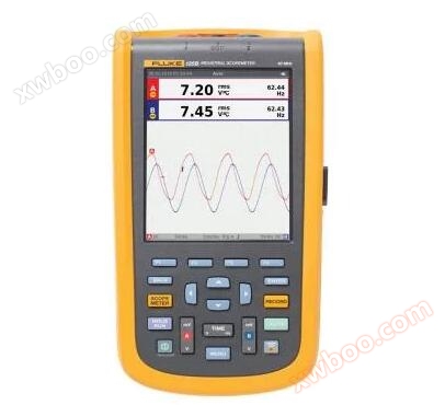
Fluke 125B Handheld Oscilloscope
Fluke125B handheld oscilloscope main parameters: dual channel
Product details
Main parameters of Fluke 125B handheld oscilloscope:
Dual channel, 40MHz bandwidth, 40MS/s real-time sampling rate, 5000 digit true RMS digital multimeter, graphic recorder function, power and harmonic measurement function, BusHealth testing function, 5.7-inch color active matrix TFT screen, USB interface
Main features of Fluke 125B handheld oscilloscope:
The 120B series industrial Scope Meter testing tool has innovative features designed specifically to help technicians troubleshoot and obtain the necessary information faster, ensuring the normal operation of the system. No manual measurement adjustment is required to use Connect and View ™ Trigger and set technology to display waveforms, and use Fluke IntellaSet ™ The technology automatically displays relevant measurement values. This oscilloscope can capture and record intermittent events that are difficult to detect through the Recorder Event Detect function, making it convenient for technicians to view and analyze.
Dual input digital oscilloscope and multimeter
40 MHz or 20 MHz oscilloscope bandwidth
Two 5000 digit true RMS digital multimeters
Connect-and-View ™ Trigger implementation is simple and easy to use, no manual operation required
IntellaSet ™ Technology can automatically and intelligently adjust numerical readings based on measured signals
Dual input waveform and instrument reading recorder, capable of trend analysis of long-term data
Recorder Event Detect can capture elusive intermittent signals on repetitive waveforms up to 4 kHz
Oscilloscope with shielded test leads, capable of measuring resistance and continuity
Resistance, continuity, diode, and capacitance measurements
Power measurement (W, VA, VAR, PF, DPF, Hz)
Voltage, current, and power harmonics
Check whether the industrial network meets the specified reference level through BusHealth physical layer testing
Save or call data and instrument settings
Instrument settings can be saved according to the testing sequence for daily maintenance or the most commonly used testing processes
External optically isolated USB interface for transmitting, archiving, and analyzing oscilloscope or instrument data
Connect the optional WiFi adapter with built-in USB port to wirelessly transfer information to PC, laptop or Fluke Connect ® Mobile applications*
Windows ® FlukeView Version ® ScopeMeter ® software
Adopting a sturdy and durable design, it meets the 3g anti vibration, 30g seismic, and IP51 rated protection level requirements specified in EN/IEC60529
Highest industrial safety level: CAT IV 600 V safety level
Lithium ion rechargeable battery, capable of continuous operation for seven hours (with a charging time of four hours)
*Not all models are available in all regions. Please consult your local Fluke representative.
Connect-and-View ™ Triggering can achieve instantaneous and stable display
Oscilloscope users are well aware of how difficult it is to trigger. If the wrong settings are used, it may lead to unstable waveform capture and sometimes even result in incorrect measurement data. Fluke's unique Connect and View ™ Trigger technology can identify signal characteristics and automatically set the correct trigger, providing stable, reliable, and repeatable display. Connect-and-View ™ The trigger is specially designed to be applicable to almost any signal, including electric drive and control signals - without the need to adjust parameters or even touch buttons. Even rapid and continuous measurements of multiple test points can immediately identify changes in signals and automatically adjust settings, providing stable display.
IntellaSet ™/ Automatic reading
Through Fluke IntellaSet ™ The automatic reading function of the technology adopts a dedicated algorithm to intelligently analyze the measured waveform and automatically display the most appropriate measurement value on the screen. Compared with the past, you can easily obtain the required data. For example, when the measured waveform is a line voltage signal, Vrms and Hz readings will be automatically displayed, but if the measured waveform is a square wave, V peak to peak value and Hz readings will be automatically displayed. Through IntellaSet ™ Technology and Connect and View ™ Automatically triggered, you can not only obtain the correct waveform, but also get appropriate readings. The entire process does not require touch buttons.
Utilizing Fluke Connect and View ™ And IntellaSet ™ Technology allows you to quickly access the data you need.
The normal operation of industrial equipment requires a reliable power supply, and key power measurement values can be obtained through dual input.
For single-phase or three-phase balanced systems, industrial Scope Meter ® The dual input of the 120B series can measure the ac+dc rms voltage of channel A and the ac+dc rms current of channel B. Subsequently, Fluke 125B will perform calculations; Frequency, phase angle, active power (kW), reactive power (VA or var), power factor (PF) or displacement power factor (DPF), and for all phases in a three-phase system with the same voltage and current, the power value of the three-phase system can also be calculated. This can be applied to balancing systems and resistive loads.
Easily obtain key power characteristics to verify system power supply.
harmonic measurement
Harmonics are periodic distortions of voltage, current, or power sine waves. Harmonics in power distribution systems are usually caused by nonlinear loads, such as switch mode DC power supplies and variable speed motor drives. Harmonics can cause overheating of transformers, conductors, and motors. In the harmonic function, the testing tool can measure up to the 51st fundamental wave. At the same time, relevant data such as DC component, THD (total harmonic distortion), and K factor can be measured to comprehensively understand the electrical status of healthy loads.
The harmonic spectrum overview with cursor can measure the percentage distortion relative to the fundamental wave.
Easily diagnose intermittent faults using comprehensive recording mode
The most difficult faults to find are those that occasionally occur - intermittent events. These intermittent faults may be caused by improper connections, dust, dirt, corrosion, broken wires, or damaged joints. Other factors such as line interruption, sag, or motor start-up and shutdown can also cause intermittent events, leading to equipment shutdown. When the above situation occurs, you may not be able to discover it on site. However, through Fluke Scope Meter ® Testing tools can easily detect these faults. You can plot the minimum and maximum peak measurement values, or record the waveform trajectory. Meanwhile, the expandable micro SD memory card can record up to 14 days of operation. The recorder is also equipped with Recorder Event Detection, making it more powerful and easier to detect and record intermittent faults compared to the past. You only need to set the threshold value of the instrument reading or oscilloscope trajectory to mark the deviation as a unique event. You can easily identify faults without retrieving large amounts of data, and quickly move from one marked event to the next, while also accessing the complete dataset.
Quickly display recorded events to identify and resolve intermittent faults.
Industrial BusHealth Test can determine the electrical signal quality of industrial buses
BusHealth Test can analyze the electrical signals of industrial buses or networks and provide clear "good", "weak" or "poor" indicators for all relevant parameters, which are displayed next to the actual measured values. Compare the measured values with standard values based on the selected bus type (CAN bus, Profi bus, Foundation fieldbus, RS-232, etc.), or set unique reference values if there are different tolerance requirements. When the electrical signal passes through the network, Fluke 125B can verify the quality of the electrical signal without viewing the data content. In addition, 125B checks signal level and speed, transition time, and distortion, and compares them with appropriate standards to help you detect errors such as improper line connections, poor contacts, grounding errors, or incorrect terminations.
Quickly understand the simulation characteristics of the physical layer of industrial fieldbus signals.
One test lead can measure multiple electrical parameters
High frequency waveform, instrument, capacitance, and resistance measurements can be completed with only one set of shielded test leads, and continuity checks can also be performed. No need to waste time searching for or replacing leads.
In addition to displaying waveforms, a single testing tool can also measure volts, ohms, amperes, or capacitance.
Windows ® FlukeView Version ® ScopeMeter ® software
Integrate Scope Meter 120B with FlukeView ® Software can be used in conjunction to achieve more functions:
Save the color screenshot of the device to a PC
Attach screenshots to your reports and documents
Capture waveform data using the Scope Meter testing tool and save it to your PC
Create and archive waveform references for easy comparison
Copy waveform data into a spreadsheet for detailed analysis
Using cursor for parameter measurement
Add user comments to the instrument settings and send them to the device for operator reference and use as operating instructions
Fluke 125B Industrial Handheld Oscilloscope (40 MHz)
including:
Fluke 125B Handheld Oscilloscope
Armored test wire with black grounding wire
Black test wire (grounding)
Hook shaped test clip (red, blue)
Banana to BNC Adapter (black, 1 piece)
10: 1 Voltage probe
I 400s AC current clamp
USB corner adapter
Wi Fi USB adapter*
Switch mode power supply, adapter/battery charger
Rechargeable lithium-ion battery pack
Online inquiry
-
Contacts
-
Company
-
Telephone
-
Email
-
WeChat
-
Verification Code
-
Message Content
-