
VIP member

Cement expansion simulation test device
Cement expansion simulation test device: It can simulate the expansion law of cement samples under high temperature and high pressure conditions. This
Product details
supplyCement expansion simulation test device,Cement expansion simulation test deviceQuotation,Purpose,Where can it be sold,Professional production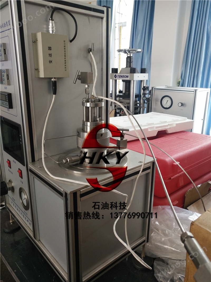
- Equipment functions
It can simulate the expansion law of cement samples under high temperature and high pressure conditions. This has important reference and guidance significance for studying the stability of cement, adopting scientific and economic decision-making, and researching and producing inhibitory expansion agents.
2、 Main technical parameters:
(1) Work pressure: 0-10MPa
(2) Power supply: 220V 50Hz
(3) Measurement range: 0 to ± 10 cm3
(4) Measurement accuracy: ≤ 0.05 cm3
(5) Sample dosage: 20-60ml
(6) Dimensions: Approximately 500 × 325 × 750mm (± 20mm)
(7) Equipped with an air filter: It can remove impurities such as oil and water from the air.
(8) Equipped with an automatic metering system.
(9) Sample container material: approximately 316L
3、 Instrument composition:
It mainly consists of a testing section, a pressurization section, a heating section, and a data acquisition and processing section.
Testing section
3.1.The sample room (expansion testing room) is mainly used for installing samples and serves as a testing site. It has displacement sensors and temperature control probe interfaces at the top, with an internal software of about 240ml and a pressure of 25MPa. It is designed for a maximum temperature of 150 ℃ and a temperature control accuracy of ± 1 ℃. The test fluid enters the sample chamber through the bottom hole and gradually submerges the core cup. The middle fluid hole is mainly used to connect the loading pressure pipeline and the pressure sensor testing end. There are two structural forms of the sample room for reference in production and design.
3.2.Displacement sensor
The displacement sensor adopts Beijing Jinghaiquan GA series products, which are separate from the LVDT and transmitter circuits. The model HTGA-10 high-precision displacement sensor is selected, with a range of 0-50mm, an accuracy of 0.1%, a working voltage of ± 12V, an output signal of 4-20mA, a withstand voltage of 30MPa, and a working temperature of 0-200 ℃.
Features: Tight and durable, high reliability;
Application: Installation in narrow spaces, convenient for simultaneous measurement and testing of multiple points on multiple sides, workpiece positioning, metallurgical and chemical industries, and ordinary temperature and humidity environments;
3.3.Pressure section
The pressurization part mainly consists of gas pressure reducing valves, pressure sensors, temperature sensors, secondary instruments, etc.
The gas pressure reducing valve adopts a high-pressure regulating valve, with an inlet pressure of 2500PSI and an outlet pressure of 1500PSI, used for precise control of gas injection pressure in the system. At the same time, a protective filter is installed at the front end of the pressure reducing valve. The filter is mainly used to filter the solid particle pollutants of the fluid to ensure the purity of the fluid medium entering the system, and the sealing of the middle note pressure regulating valve of the protection system is reliable.
The pressure sensor is selected from the Huaqiang brand, with a range of 16MPa and an accuracy of 0.25%. The pressure value is directly displayed by the secondary instrument and computer communication is achieved through RS232/485 interface.
3.4.Heating section
The heating part is mainly composed of temperature sensors and measuring instruments. The secondary instrument adopts artificial intelligence display control instrument with PID regulation, which can effectively control thermal inertia. The numerical value is directly displayed by the secondary instrument and computer communication is achieved through RS232/485 interface.
3.5.Data Acquisition Section
PLCThe acquisition and control system is mainly used for the acquisition and control of temperature, pressure, and displacement in the system. At the same time, the PLC screen interface displays the system process, experimental data, etc. The PLC system is equipped with overpressure and overtemperature alarm devices or automatic shutdown protection programs. At the same time, PLC can record temperature, pressure and other data.
4、 Device Description:
We can provide the required pressure for the experiment to meet different testing needs. Under the selected experimental conditions, the instrument can accurately measure the amount and pattern of change in sample volume over time. The instrument automatically collects various experimental parameters, processes the data, displays the test results in real time, and can store and display the experimental rules, curves, and data. The instrument adopts a complete machine design structure, with high sensitivity, stable operation, and easy operation. The instrument has multiple safety insurance and alarm measures to ensure safe use.
The device mainly consists of the following components: pressurization component - providing the required safe pressure for pressure testing; Test components - carrying cement slurry samples and converting volume variables into corresponding electrical signals; Signal conversion component - converts the measured volume variable signal and pressure signal and transmits them to the computer system. Data acquisition and processing system - collects and processes various measurement data, displays and stores measurement parameters and change curves, and prints test reports.
(1) Process and Testing Components
The process of the device adopts a single channel series connection working mode, separating the test medium from the pressurized medium through an isolation device to avoid mixing the two and affecting the test results. Using a gas source as a pressure source, simulate the pressure requirements by increasing the pressure to different well depths through a boosting device. Each process segment is connected by a switch valve, which makes it easy to perform process combination control. The inlet end is equipped with a pressure relief valve, and the process end is equipped with an exhaust valve for easy pressure control.
The experimental process is roughly as follows: first, a certain amount of cement slurry is filled into the test cup, and the pressure and temperature are adjusted to the required conditions for the experiment. Under certain pressure and temperature conditions, the cement slurry slowly changes. The deformation is measured by sensors, and various experimental parameters are collected, processed, displayed, and printed through a data acquisition system. The experimental process data is given and the curve of the experimental process is drawn.
(2) Pressure parts
The experimental device consists of a closed-loop pressure control system consisting of a pressure source, pressure sensors, and pressure control valves to meet the pressure control requirements of the experiment. All pressure process components in the device have undergone strength verification and meet the requirements for use.
(3) Data Collection and Processing System
The main function of the data acquisition and processing system in the experimental device is to convert the electrical signals of temperature, pressure, and cement expansion or contraction from sensors into digital signals for processing, plotting, storage, display, printing, etc.
5、 Device process:
6、 Instrument outline drawing
Dimensions: Approximately 500 × 325 × 750mm (± 20mm)
7、 Operation steps
1Before operation, all valves should be closed. Open the top cover of the reaction vessel and add a certain amount of cement slurry 20-60ml into the reaction vessel. Install the piston and cover it properly.
2Heating the reaction kettle: Set the temperature of the reaction kettle and turn on the heating switch of the reaction kettle. If the pressure exceeds the experimental pressure during the heating process, the vent valve can be opened to reduce the pressure
3When the temperature is constant, if the pressure in the reaction vessel does not reach the experimental pressure, open the gas cylinder valve, set the pressure regulating valve pressure, open the pressure increasing valve until the pressure in the reaction vessel reaches the experimental pressure and temperature, and maintain constant temperature and pressure until the experiment is completed.
4After the experiment, turn off the heating switch and open the vent valve to release pressure. After the pressure relief is completed, the temperature drops to room temperature. Before removing the reactor, please wear heat-resistant gloves, remove the pressure pipeline, and take out the reactor. Use a wrench to tighten the bolt clockwise and push the sample out.
5Clean the inner wall of the kettle with clean water until it is smooth and clean, in preparation for the next experiment. (Use heat-resistant gloves throughout the entire experimental process)
8、 Maintenance
All parts of the instrument that come into contact with acidic and alkaline liquids are made of stainless steel 304 material, which has a certain degree of corrosion resistance, but it is not a one-time solution. The process manifold needs to be cleaned regularly, especially immediately with clean water after injecting corrosive liquids. When the process is not in use for a long time, fill the process manifold with oil or blow dry it with high-pressure air to prevent rust and corrosion.
If there is a malfunction that cannot be resolved, please contact the manufacturer and have our professional personnel repair and handle it for you.
9、 Security
The safe operation of the instrument involves the personal safety of the operator and the normal service life of the instrument. The manufacturer reminds the operator to pay attention to the following points:
* The power supply of the instrument must be equipped with an automatic voltage stabilization protection device.
* Ensure that all parts of the instrument have good grounding.
* The pressure of each part of the process manifold should not exceed the design pressure, especially not exceed the range of various detection instruments. Extra caution must be taken when using it.
* The valve design of the instrument is manual operation. Please pre design the test process according to the test steps. Any valve operation error may lead to the failure of the entire test.
* When operating the system at high temperatures, insulated gloves must be worn to prevent burns.
* This experiment contains corrosive liquids or gases, and the equipment must be placed in a well ventilated indoor area to prevent operators from inhaling corrosive gases and causing personal injury.
10、 Installation and debugging
Our company will dispatch specialized personnel as per your request to deliver the goods to your doorstep for installation and debugging.
11、 Fault analysis and troubleshooting
1When the reactor is pressurized and emptied, there is pressure inside the reactor but it cannot be released.
Possible reason: There are solid particles in the reaction kettle, which have blocked the discharge pipeline.
Solution: Close the pressure valve, open the vent valve or remove the pressure cap of the connecting pipeline of the kettle body, reduce the pressure inside the kettle to atmospheric pressure, remove the inlet and outlet pipelines, and clean them.
Preventive measures: After each experiment, please clean the pipeline with relevant solvents or clean water until there are no solid impurities in the discharged liquid. You can also warm it up slightly for cleaning.
2The temperature of the reaction vessel remains unchanged and is not heated.
Reason: (1) The heating indicator light on the temperature gauge does not light up: the pressure inside the kettle is higher than the set pressure, and the system automatically protects and stops heating.
(2) The heating indicator light on the temperature gauge is on: the electric heating tube or circuit is damaged.
Solution: (1) Drain some of the pressure inside the kettle, lower the pressure, and then heat it up.
(2) Please inform our company promptly if the heating element is damaged, and we will send someone to the site for repair.
Preventive measures: (1) Set a protective pressure during the experiment and constantly monitor changes in pressure and temperature inside the reaction vessel.
(2) Be careful not to pour water or other conductive liquids into the heating furnace during normal use.
12、 Maintenance and upkeep
Pay attention to the cleanliness of the equipment regularly, and clean the reaction kettle and pipelines promptly after each use.
13、 Precautions
1During the experiment, pay attention to the pressure and temperature of the kettle body. In case of emergencies, turn off the main power and open the vent valve.
2During the experiment, the reaction kettle was constantly heated, and attention should be paid not to touch the high-temperature area during operation to avoid burns.
3At no time shall conductive liquids flow into electrical components or heating furnaces.
Online inquiry
-
Contacts
-
Company
-
Telephone
-
Email
-
WeChat
-
Verification Code
-
Message Content
-