
VIP member

BXY65M10-5 Intelligent Pressure Controller
? Provides constant voltage and current excitation, can be connected to various types of sensors (diffused silicon, ceramic capacitors, ceramic resist
Product details

1overview
This series of pressure transmission controllers is an intelligent digital pressure measurement and control product that integrates pressure measurement, display, output, and control. This product is a fully electronic structure, with a front end equipped with an isolated membrane filled hydraulic resistance pressure sensor, which is composed of high-precisionA/DConversion, processed by microprocessor, displayed on site, and outputting one analog signal and five switch signals.
This pressure controller is flexible to use, easy to operate, easy to debug, and safe and reliable. Widely used in industries such as hydropower, tap water, petroleum, chemical, mechanical, hydraulic, etc., for on-site measurement, display, and control of fluid medium pressure
IIcharacteristic
·Provide constant voltage and current excitation, and can be connected to various types of sensors (diffused silicon, ceramic capacitors, ceramic resistors, etc.)
·Output multiple standard analog signals (0/4~10/20mDC 0/1~5/10VDC)
·It can display four pressure values, four status parameters, and output standard analog signals
·Button calibration and on-site setting of various parameters, easy to operate
·Multiple power supply options available (24VDC, 220VAC, 220VDC)
·1 to ± 5 relay outputs
·Ultra small temperature drift
·Applicable to the appearance of a Φ 100 standard pressure gauge
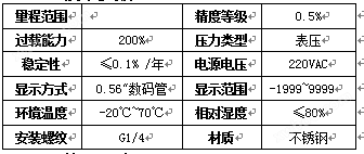
3、 Technical parameters
4、 External dimensions
5、 Installation
5.1Mechanical connection:
This product can be connected through a pressure pipe joint(M20*1.5)(Other sizes of connectors can be specified at the time of ordering) Directly installed on the hydraulic pipeline. In critical applications such as severe vibrations or impacts, pressure pipe joints can be mechanically decoupled through micro hoses.
pour:Range less than100KPaIt must be installed vertically
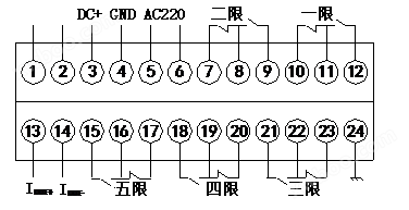
5.2Electrical connection
To prevent the impact of electromagnetic interference, the following precautions should be taken:
The line connection should be as short as possible and shielded wires should be used
Try to avoid direct contact with user devices or wiring of electrical and electronic devices that may cause interference
If a micro hose is used for installation, the housing must be separately grounded
6、 Set Function
6.1output
Example:To set the relay1For the upper limit alarm output (normally open function)4MpaSuck and less than3.95Mpato break off,; relay2For the lower limit alarm output (normally closed function)10MpaDisconnected, below9.95MpaSuck and:
Enter menu: Settings
AL1H=4.00 AL1L=3.95
AL2H=9.95 AL2L=10.00
● Press“SET”key
● Display“LOCK”(Prompt for password input)
Press the ▲ or ▼ keys to enter the password“1”,
● Press“SET”Key confirmation
Press the ▲ or ▼ keys to scroll up or down for menu selection(AL1H、AL1L、AL2H、AL2L,,,,,)
● Press“SET”Enter the selected menu with the key.
Press the ▲ or ▼ keys to change settings
● Press“SET”Confirm with the key, and if necessary, use the ▲ or ▼ keys to select other menus for modification.
After the modification is completed, press“SET”Press the key to confirm, save, and exit

Online inquiry
-
Contacts
-
Company
-
Telephone
-
Email
-
WeChat
-
Verification Code
-
Message Content
-