 
|
| The fluid flows through the sensor housing. Due to the angle between the blades of the impeller and the flow direction, the impulse of the fluid causes the blades to have a rotational torque. After overcoming the friction torque and fluid resistance, the blades rotate. After the torque is balanced, the speed stabilizes. Under certain conditions, the speed is proportional to the flow rate. Due to the magnetic conductivity of the blades, they are in the magnetic field of the signal detector (composed of permanent magnet and coil). The rotating blades cut the magnetic field lines and periodically change the magnetic flux of the coil, causing electrical pulse signals to be induced at both ends of the coil. This signal is amplified and shaped by the amplifier, forming a continuous rectangular pulse wave with a certain amplitude, which can be transmitted to the display instrument remotely to display the instantaneous flow rate or total amount of the fluid. Within a certain flow range, the pulse frequency f is proportional to the instantaneous flow rate Q of the fluid flowing through the sensor, and the flow equation is: |
| |
 |
| In the formula: |
| |
F - Pulse frequency [Hz] |
| |
K - the instrument coefficient of the sensor [1/m3], given by the calibration sheet. If [1/L] is used as the unit |
| |
 |
| |
Q - Instantaneous flow rate of fluid (under working conditions) [m3/h] |
| |
3600- Conversion factor |
|
| The instrument coefficient of each sensor is filled in the calibration certificate by the manufacturer, and the k value is set in the matching display instrument to display the instantaneous flow rate and cumulative total amount. |
| The relationship curve between the coefficient of the flowmeter and the flow rate (or Reynolds number) is shown in Figure 1. As shown in the figure, the instrument coefficient is divided into two segments, namely the linear segment and the nonlinear segment. The linear segment is about two-thirds of its working segment, and its characteristics are related to the sensor structure size and fluid viscosity. The nonlinear segment characteristics are greatly affected by bearing friction and fluid viscous resistance. When the flow rate is below the lower limit of the sensor flow rate, the instrument coefficient changes rapidly with the flow rate. When the flow rate exceeds the upper limit, attention should be paid to preventing cavitation. |
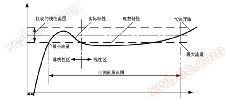 |
| Figure 1 Turbine flowmeter characteristic curve |
|
 |
| 1. The sensor is a hard alloy bearing thrust type, which not only ensures accuracy and improves wear resistance, but also has the characteristics of simple structure, firmness, and easy disassembly and assembly. |
| 2. Schematic diagram of the structure of the Foctur DN15-DN200 sensor |
|
|
| |
| 3. Schematic diagram of the sensor structure for Foctur DN4-DN10 |
 |
| 1. Filter 2. Front straight pipe section 3. Leading fluid 4. Impeller 5. Sensor housing 6. Rear guiding fluid 7. Rear straight pipe section |
| |
| 4. Schematic diagram of the structure of the Foctur DN15-DN50 sensor |
 |
| 1. Spring clamp 2. Sensor housing 3. Leading fluid 4. Impeller 5. Rear guiding fluid |
| |
| 5. Pre amplifier structure and composition |
 |
| 1. Pre amplifier housing 2. Coil skeleton 3. Coil 4. Pure iron rod 5. Permanent magnetic steel |
 |
| 1. High precision, generally up to ± 1% R, ± 0.5% R, and high-precision models up to ± 0.2% R; (R refers to reading error); |
| 2. Good repeatability, short-term repeatability can reach 0.05% to 0.2%. It is precisely because of good repeatability that frequent calibration or online calibration can achieve extremely high accuracy, and flow meters are preferred in trade settlement; |
| 3. Local display, instantaneous flow and cumulative flow; |
| 4. Output pulse frequency signal, 4-20mA, 485 communication; |
| 5. Can obtain high frequency signals with strong signal resolution; |
| 6. Wide range ratio, up to 1:20 for medium and large apertures, and 1:10 for small apertures; |
| 7. Compact and lightweight structure, easy installation and maintenance, and high circulation capacity; |
| 8. Suitable for high voltage measurement, the sensor body does not need to be perforated, making it easy to make high voltage instruments; |
| 9. There are various types of specialized sensors that can be designed according to the specific needs of users, such as low-temperature, bidirectional, downhole, and sand mixing specialized sensors. |
| 10. Can be made into an insertion type, suitable for measuring large diameters, with low pressure loss, low price, can be removed without interruption, and easy installation and maintenance. |
| 11. Humanized menu and interface based on dot matrix display, with bright backlight, supporting both Chinese and English languages, suitable for various customer groups; |
| 12. Support temperature and pressure measurement, convenient for gas medium temperature and pressure compensation needs; |
| 13. Support flow rate conversion display function, convenient for on-site viewing of current flow rate; |
| 14. Support split screen display function, which can enlarge and display single or two parameters (temperature, pressure, operating conditions, flow rate and flow rate under standard conditions, etc.) on the screen; |
| 15. Simulation output function, supporting 4-20mA current simulation and frequency output simulation, convenient for on-site non real current debugging; |
| 16. Supports 4-20mA output, pulse (equivalent) output, alarm output, and RS485 communication output. |
|
 |
| 1. Main technical parameters |
| Measurement medium |
No impurities, no strong corrosiveness, low viscosity liquid |
| Execution standards |
Turbine flow sensor (JB/T9246-1999) |
| Verification regulations |
Turbine flowmeter (JJG1037-2008) |
| Instrument caliber and connection method |
flange type |
DN15-DN200 |
| Threaded connection type |
DN4-DN50 |
| Clamp connection type |
DN25-DN50 |
| Flange standard |
Conventional standards |
GB/T9113-2000 |
| Other standards |
International pipe flange standard |
Such as German standard DIN, American standard ANSI, Japanese standard JIS |
| Domestic pipe flange standards |
Such as the standards of the Ministry of Chemical Industry and the Ministry of Machinery |
| Thread specifications |
Conventional specifications |
British pipe thread (external thread) |
| Other specifications |
Internal thread, NPT thread, etc |
| Accuracy level and corresponding repeatability |
Accuracy level |
±1%R |
±0.5%R |
± 0.2% R (customization required) |
| Linearity |
≤0.15% |
≤0.1% |
≤0.03% |
| Range ratio |
1:10; 1:15; 1:20 |
| Instrument material |
304 stainless steel; 316 stainless steel |
| Temperature of the tested medium (℃) |
-20℃~+110℃ |
| Verification conditions |
environment condition |
ambient temperature |
20℃ |
| relative humidity |
65% |
| Verification device |
Standard table method liquid flow verification device |
| Static mass method liquid flow verification device |
| Usage conditions |
ambient temperature |
-20℃~+60℃ |
relative humidity |
5%~90% |
| atmospheric pressure |
86Kpa~106Kpa |
| output signal |
Pulse frequency signal |
| Two wire 4-20mA DC current signal |
| 485 communication |
| Power supply |
24V DC |
| transmission distance |
≤1000m |
| Signal line interface |
Basic type: Hirschman connector, explosion-proof type: internal thread M20 * 1.5 |
| Explosion proof grade |
Basic type: Non explosion proof product, Explosion proof type: Exd II CT6 Gb |
| Protection level |
IP65 |
|
| |
| 2. Caliber Flow Comparison Table |
| Instrument diameter (mm) |
Normal flow range (m3/h) |
Expand flow range (m3/h) |
Instrument diameter (mm) |
Normal flow range (m3/h) |
Expand flow range (m3/h) |
| DN4 |
0.04~0.25 |
0.04~0.4 |
DN50 |
4~40 |
2~40 |
| DN6 |
0.1~0.6 |
0.06~0.6 |
DN65 |
7~70 |
4~70 |
| DN10 |
0.2~1.2 |
0.15~1.5 |
DN80 |
10~100 |
5~100 |
| DN15 |
0.6~6 |
0.4~8 |
DN100 |
20~200 |
10~200 |
| DN20 |
0.8~8 |
0.45~9 |
DN125 |
25~250 |
13~250 |
| DN25 |
1~10 |
0.5~10 |
DN150 |
30~300 |
15~300 |
| DN32 |
1.5~15 |
0.8~15 |
DN200 |
80~800 |
40~800 |
| DN40 |
2~20 |
1~20 |
|
|
|
|
 |
| 1. Flange connection type |
 |
Instrument diameter (mm) |
Nominal pressure (Mpa) |
L (mm) |
H (mm) |
D (mm) |
D1 (mm) |
D (mm) |
n |
T (mm) |
| DN15 |
4.0Mpa |
75 |
300 |
95 |
65 |
14 |
4 |
14 |
| DN20 |
4.0Mpa |
90 |
305 |
105 |
75 |
14 |
4 |
16 |
| DN25 |
4.0Mpa |
100 |
310 |
115 |
85 |
14 |
4 |
16 |
| DN32 |
4.0Mpa |
140 |
325 |
140 |
100 |
18 |
4 |
18 |
| DN40 |
4.0Mpa |
140 |
335 |
150 |
110 |
18 |
4 |
18 |
| DN50 |
4.0Mpa |
150 |
350 |
165 |
125 |
18 |
4 |
20 |
| DN65 |
1.6Mpa |
180 |
365 |
185 |
145 |
18 |
4 |
20 |
| DN80 |
1.6Mpa |
200 |
380 |
200 |
160 |
18 |
8 |
20 |
| DN100 |
1.6Mpa |
220 |
400 |
220 |
180 |
18 |
8 |
22 |
| DN125 |
1.6Mpa |
250 |
430 |
250 |
210 |
18 |
8 |
22 |
| DN150 |
1.6Mpa |
300 |
460 |
285 |
240 |
22 |
8 |
24 |
| DN200 |
1.6Mpa |
360 |
510 |
340 |
295 |
22 |
12 |
26 |
|
| |
| 2. Threaded connection type |
 |
Instrument diameter (mm) |
Nominal pressure (Mpa) |
L (mm) |
H (mm) |
Thread specification (G) |
| DN4 |
6.3Mpa |
275 |
260 |
G1/2 |
| DN6 |
6.3Mpa |
275 |
260 |
G1/2 |
| DN10 |
6.3Mpa |
455 |
260 |
G1/2 |
|
 |
Instrument diameter (mm) |
Nominal pressure (Mpa) |
L (mm) |
H (mm) |
Thread specification (G) |
| DN15 |
6.3Mpa |
75 |
265 |
G1 |
| DN20 |
6.3Mpa |
80 |
265 |
G1 |
| DN25 |
6.3Mpa |
100 |
270 |
G5/4 |
| DN32 |
6.3Mpa |
140 |
290 |
G2 |
| DN40 |
6.3Mpa |
140 |
290 |
G2 |
| DN50 |
6.3Mpa |
150 |
305 |
G5/2 |
|
| |
| 3. Clamp connection type |
 |
Instrument diameter (mm) |
Nominal pressure (Mpa) |
L (mm) |
H (mm) |
| DN25 |
1.6Mpa |
100 |
275 |
| DN32 |
1.6Mpa |
140 |
275 |
| DN40 |
1.6Mpa |
140 |
285 |
| DN50 |
1.6Mpa |
150 |
300 |
|
| Connect the flange and standard HG20593-97. If the user requires a special pressure rating, they can negotiate and place an order. If an explosion-proof sensor is needed, please specify it in the order. |
 |
 
|
| Material selection |
| Connection method |
Material (regular type) |
Material (special type) |
| Flange connection type |
Body |
304 stainless steel |
flange |
304 stainless steel |
flange |
316 |
| baffle |
Table body/diversion body |
316 |
| snap ring |
impeller |
2cr13 stainless steel |
impeller |
Dual phase steel |
| Tu Fu Te Long |
| Threaded connection type |
Straight pipe section |
304 stainless steel |
Body |
304 stainless steel |
Body |
316 |
| baffle |
nut |
baffle |
316 |
| snap ring |
impeller |
2cr13 stainless steel |
impeller |
Dual phase steel |
| Tu Fu Te Long |
| Clamp connection type |
baffle |
304 stainless steel |
Body |
304 stainless steel |
Body |
316 |
| snap ring |
impeller |
2cr13 stainless steel |
impeller |
Dual phase steel |
| Tu Fu Te Long |
|
| Note: Special materials need to be determined according to the actual diameter requirements of the sensor. |
 |
|
1. Wiring terminal diagram
|
 |
| 2. The meaning of wiring terminals is as follows |
| communication |
A |
RS485 communication A |
| B |
RS485 communication B |
| 24V DC |
+ |
24V DC power input (positive) |
| - |
24V DC power input (negative) |
| electric current |
I+ |
4~20mA output |
| frequency |
P+ |
24V frequency, pulse output |
| call the police |
AH |
Upper limit alarm output |
| AL |
Lower limit alarm output |
|
| |
| 3. Wiring diagram |
| ① Two wire 4-20mA output |
|
② Three wire system with 4-20mA output |
 |
|
 |
| ③ 24V frequency, pulse output |
|
④ RS485 communication interface output |
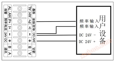
| Note: The negative terminal of frequency output and the negative terminal of DC 24V are common terminals; The frequency and pulse output must be wired according to a three wire system, as shown in the diagram below. The two-wire system does not support frequency and pulse output; The default factory frequency and pulse output are active outputs; The default factory frequency and pulse output idle level are high level, and low level when pulses are received. |
|
Note: RS485 communication must be wired according to a three wire system, as shown in the diagram below. Two wire system does not support RS485 communication. |
 |
|
 |
| ⑤ Alarm signal output |
|
⑥ Power supply |
| Note: The alarm output must be wired according to the three wire system, as shown in the diagram below. The two wire system does not support alarm output. |
|
|
 |
|
When the flow meter requires flow pulse signal output, an external power supply with a supply voltage of+24V DC is required (Three line system). |
| When the flowmeter requires a 4-20mA current signal output, a+24V DC external power supply (two-wire or three wire system) needs to be added. |
| When the flowmeter requires RS485 data communication, a+24V DC power supply needs to be added. (Three line system). |
| |
|
 |
| 1. Installation conditions and location |
| The pipeline must be completely filled with liquid. It is important to keep the pipeline completely filled with liquid at all times, otherwise the flow display may be affected and measurement errors may occur. |
 |
| Avoid bubbles. If bubbles enter the measuring tube, the flow display may be affected, which may lead to measurement errors. |
 |
|
| |
| 2. Typical installation pipeline system diagram of turbine flowmeter |
 |
| |
| 3. Requirements for installing straight pipe sections |
| The length of the straight pipe section of the turbine flowmeter is sensitive to the distortion of flow velocity distribution and rotational flow inside the pipeline. When entering the sensor, turbulence should be fully developed. Therefore, necessary straight pipe sections or rectifiers should be equipped according to the type of upstream flow resistance components of the sensor, and the length of the straight pipe sections at the inlet and outlet should be required. |
| type |
Installation conditions |
type |
Installation conditions |
| General situation |
 |
90 ° elbow |
 |
| Two 90 ° elbows on the same plane |
 |
Two 90 ° elbows on different planes |
 |
| contracted pipe |
 |
Half open valve |
 |
| Fully open the valve |
 |
Half open valve |
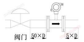 |
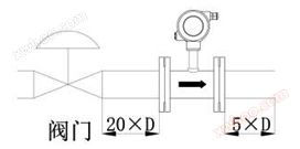
| If the situation of the upstream blocking component is unclear, it is generally recommended that the length of the upstream straight pipe section be no less than 20D and the length of the downstream straight pipe section be no less than 5D. If the installation of the control cannot meet the above requirements, a rectifier can be installed between the blocking component and the sensor. When installing sensors outdoors, measures should be taken to avoid direct sunlight and rain. |
|
 |
| Fault phenomenon |
Possible reasons |
Elimination methods |
| When the fluid flows normally, there is no display, and the total count counter does not increase in words |
1. Check for open circuits or poor connections in the power and signal wires. |
1. Use an ohmmeter to troubleshoot the fault point. |
| 2. Check the internal fault of the sensor. If the above confirmation is normal or the fault is eliminated, but there is still a fault phenomenon, it indicates that the fault is inside the sensor flow channel. Check whether the impeller touches the inside of the sensor, whether it is stuck or not, and whether there are impurities or fractures in the shaft and bearings. |
2. After removing foreign objects and cleaning or replacing bearings and other parts, re inspection should be carried out to obtain new instrument coefficients. |
| No flow reduction operation was performed, but the flow display gradually decreased |
1. Is the filter clogged? If the differential pressure of the filter increases, it indicates that debris has clogged. |
1. Clean the filter |
| 2. The valve core on the flow sensor is loose, and the valve opening automatically decreases. |
2. Judging from whether the valve handwheel is effectively adjusted, repair or replace it after confirmation. |
| 3. The sensor impeller is obstructed by debris or foreign objects enter the bearing clearance, increasing resistance and slowing down speed. |
3. Remove the sensor and clear it, and recheck if necessary. |
| The fluid does not flow, the flow rate display is not zero, or the indication is unstable |
1. Poor grounding of the transmission line, external interference signals mixed into the input terminal of the display instrument. |
1. Check if the shielding layer and terminals are well grounded. |
| 2. Pipeline vibration causes the impeller to shake, resulting in false signals. |
2. Reinforce the pipeline or clamp brackets before and after the sensor to prevent vibration. |
| 3. The failure to close the shut-off valve resulted in leakage on the instrument display. |
3. Check or replace the valve. |
| The difference between the displayed value and the empirical evaluation value is significant |
1. Internal faults in the sensor flow channel, such as fluid corrosion, wear, and obstruction by debris causing abnormal rotation of the impeller, changes in instrument coefficient, blade corrosion or impact, top deformation, affecting normal cutting of magnetic field lines, abnormal output of detection coil signals, and changes in instrument coefficient; The fluid temperature is too high or too low, the shaft and bearings expand or contract, and the clearance changes too much, causing the impeller to rotate abnormally and the instrument coefficient to change. |
1. (1-4) Identify the cause of the malfunction and find solutions based on the specific reasons.
2. Replace the components.
3. Replace the appropriate sensor.
|
| 2. Insufficient back pressure of the sensor leads to cavitation, which affects the rotation of the impeller. |
| 3. Due to reasons related to pipeline flow, such as the absence of a check valve causing reverse flow, the bypass valve not being tightly closed, and leakage. There is a significant distortion in the flow velocity distribution upstream of the sensor (such as caused by the upstream valve not being fully opened), or there is a significant change in viscosity of pulsating liquid due to temperature. |
| 4. Internal malfunction of the display device. |
| 5. The failure and demagnetization of the permanent magnet material components in the detector can also affect the measured values when the magnetism weakens to a certain extent. |
| The actual flow rate flowing through the sensor has exceeded the flow range specified by the sensor. |
|
 |
 |
 |
 |
|
 |
 |
 |
| |
| |
| |
| |
| |
| |
| |
| |
| |
| |


