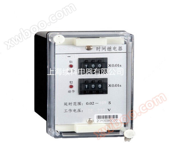
DESCRIPTION
SS-60、 61 and 62 type static time relays
1、 Purpose:
SS-60, 61, and 62 high-precision time relays (hereinafter referred to as relays) are used for automatic delay conversion in various control or protection circuits.
2、 Structure and Principle
The relay adopts JK-11K, H, and Q type housing, and its external dimensions, rear terminals, and installation opening diagram are shown in Appendix 3. The wiring of the rear terminals is shown in Figure 1, and the schematic wiring diagram is shown in Figure 2.
A relay consists of several parts, including a rectifier circuit, a voltage regulator circuit, an oscillator, a counter, and an outlet circuit. A low-power CMOS integrated circuit is used, which has a 14 level serial carry binary counter inside. The clock input terminal has a series inverter available for use, and an RC oscillator is formed by external resistors and capacitors. Adjusting R9 can change its oscillation frequency. When a clock pulse appears at the input of the counter, the counter starts counting, and each output can achieve different delay requirements according to different frequency divisions. The CMOS integrated circuit has a reset terminal "R". When the power is turned on, the "R" terminal applies a "1" level, and the counter output is reset to zero. The output terminals Q4 to Q10 and Q12 to Q14 are used to select the delay range of the relay. The output signal of the counter is driven by a transistor to execute the relay action.


Figure 1 Rear Terminal Wiring Diagram

Figure 2 Schematic wiring diagram
3、 Technical requirements
1. Rated voltage: AC 220, 127, 110, 100V.
2. Delay range: see Table 1.
3. Action and return values of relays
The action value of the relay shall not exceed 80% of the rated voltage, and the return value shall not be less than 5% of the rated voltage.
4. Delay consistency
At the reference temperature, when the rated voltage is applied, the delay consistency of the relay is not greater than 1% of the set value. Its meaning refers to the ratio of the difference between the maximum and minimum values of the actual action values measured 10 times at any set point to the arithmetic mean of the 10 measurements.
5. Average error of delay setting value
At the reference temperature, apply the rated voltage to the relay
Table 1
|
ordername
|
Maximum setting value
|
Delay range
|
|
1
|
37.5s
|
7.5s~37.5s
|
|
2
|
75s
|
15s~75s
|
|
3
|
150s
|
30s~150s
|
|
4
|
5min
|
1min~5min
|
|
5
|
10min
|
2min~10min
|
|
6
|
20min
|
4min~20min
|
|
7
|
40min
|
8min~40min
|
|
8
|
160min
|
32min~160min
|
|
9
|
320min
|
64min~320min
|
|
10
|
640min
|
128min~640min
|
6. Temperature impact
When the temperature changes within the nominal range, the variation of the relay delay setting value should not exceed twice the values specified in sections 4 and 5.
7. Voltage impact
When the input influence changes within the working range, the variation of the relay delay setting value shall not exceed twice the specified values of Type 4 and Type 5.
8. Power consumption: At rated voltage, the power consumption of the relay complies with the provisions of Table 2:
Table 2
|
rated voltageAC
|
Power consumption
|
|
220V
|
not more than3.5VA
|
|
127V
|
not more than2VA
|
|
110V
|
not more than1.7VA
|
|
100V
|
not more than1.5VA
|
DC inductive (τ=5ms) circuit, U≤250V,I≤0.5A, 30W; In the communication loop (cos Φ=0.4), U≤250V,I≤1A, It is 100VA.
10. Dielectric strength
The conductive circuits of the relay are connected together with the exposed non charged metal parts and the shell, and can withstand an AC voltage of 2kV (effective value) and 50Hz for 1 minute, without insulation breakdown or flashover phenomenon.
11. Lifespan
The electrical lifespan is 5 × 10³ times, and the mechanical lifespan is 104 times.
12. Weight
The weight of the relay is approximately 1kg.
4、 Debugging method
1. Adjust the potentiometer knob pointer to the setting scale I position, adjust the voltage regulator to reach the rated voltage value, close the switch, and start the relay delay. When the delay is over, the red LED light on the panel lights up, and the output relay action terminal is connected and remains in this state until the power is disconnected, and the relay returns to complete one delay action.
2. The nameplate setting values of 1-5 are divided and multiplied. If the delay setting range is 8min~40min, the setting value at 1 o'clock is 40/5=8min, and at 2 o'clock it is 8 × 2=16min.
3. The delay consistency and average error of the relay can be measured according to the provisions of Article 3, Paragraph 4 and Article 3, Paragraph 5.
5、 Ordering Notice
Please specify the model, name, rated voltage, delay range, and installation method of the relay when placing an order.

