|
| 1. Sensor principle |
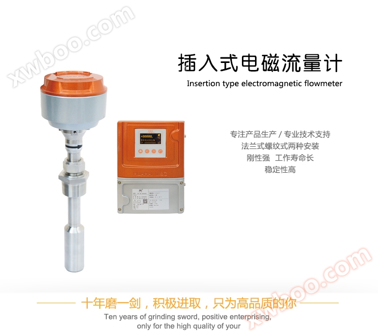
| A sensor is actually a liquid flow velocity measuring instrument. It is a flow velocity measuring instrument made using the principle of Faraday's law of induction. Figure 1 is a schematic diagram of the basic working principle of an insertion type flowmeter. Insert a small electromagnetic flow sensor into a designated position in the measured pipeline using a long rod. When a conductive fluid flows vertically through the working magnetic field of the sensor (when the converter provides excitation current to the sensor, a working magnetic field is generated in the excitation system composed of excitation coils), it is equivalent to the conductor cutting magnetic field lines in the magnetic field. According to Faraday's law of induction, an induced electromotive force is generated at both ends of a conductor. The induced electromotive force is detected by a pair of electrodes in contact with the fluid. The magnitude of electromotive force is directly proportional to the magnetic induction intensity B, the distance L between the two poles, and the average flow velocity of the fluid. Namely E=B · L · V (volts) |
| In the formula: E - induced electromotive force, V; B - magnetic field strength, T; L - distance between two electrodes, m; |
| V - Flow velocity through the sensor (i.e. representing the particle flow velocity at the specified insertion point of the measured pipeline), m/s |
| K - coefficient. |
|
 |
|
| 2. Working principle of circuit |
| |
 |
| |
|
3. Structural composition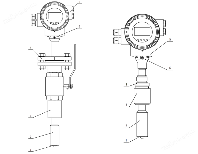
1. Electrode 2. Probe housing 3 Valve installation connection seat/threaded base 4. Connection flange/threaded joint 5. Converter 6. Grounding screw
|
 |
| 1. The sensor has no moving parts inside, simple structure, strong rigidity, and long working life. |
| 2. The sensor probe is made using the latest technology, greatly improving product stability. |
| 3. The plug-in electromagnetic structure can be easily installed and disassembled without stopping water supply under low voltage or pressure conditions. Therefore, it is highly suitable for fluid measurement in existing pipelines and facilitates maintenance and repair of instruments. |
| 4. The measurement accuracy is not affected by changes in physical parameters such as temperature, pressure, density, viscosity, and conductivity (as long as the conductivity is greater than 20 μ s/cm) of the measured medium; The sensor has almost no pressure loss and extremely low energy loss. |
| 5. Compared to general flow meters, the manufacturing and installation costs are lower. Especially suitable for flow measurement of large and medium-sized pipelines. |
| 6. There are two installation structures to choose from: flange type and threaded type. |
|
 |
1. Main technical parameters
| model |
Focmag3401 |
Focmag3402 |
| The nominal Tongjing |
DN150-DN800 |
DN200-DN1800 |
| Basic error |
±2.0%F.S |
| flow rate range |
0.5m/s-10m/s |
| ambient temperature |
-20-60℃ |
| medium temperature |
-20-80℃ |
| Connection method |
Flange connection DN40 PN1.6MPa |
Threaded connection 1/2 NPT |
| working pressure |
0.25MPa-1.6MPa |
| output signal |
Current output: 4-20mA Frequency output: 0-5kHz |
| Power consumption |
≤15W |
| Power supply |
220V AC 50HZ, 24V DC |
| Electrode material |
316L |
| communication interface |
RS-485; HART |
| Installation form |
Integrated; Split type |
| Electrical interface |
M20 * 1.5 thread |
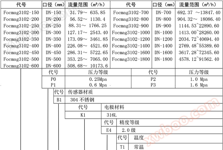
2. Measurement range
| Caliber (mm) |
Measurement range (m3/h) |
Caliber (mm) |
Measurement range (m3/h) |
| DN150 |
31.79~ 635.85 |
DN700 |
692.37 ~13847.40 |
| DN200 |
56.52 ~ 1130.4 |
DN800 |
904.32~ 18086.40 |
| DN250 |
88.31 ~ 1766.25 |
DN900 |
1144.5~ 22890.60 |
| DN300 |
127.17~ 2543.40 |
DN1000 |
1413.0~ 28260.00 |
| DN350 |
173.09~ 3461.85 |
DN1200 |
2034.7~ 40694.40 |
| DN400 |
226.08~ 4521.60 |
DN1400 |
2769.4~ 55389.60 |
| DN450 |
286.31~ 5722.65 |
DN1600 |
3617.2~ 72345.60 |
| DN500 |
353.25~ 7065.00 |
DN1800 |
4578.1~ 91562.40 |
| DN600 |
508.68~ 10173.6 |
|
|
|
 |
|
|
|

|
|
 |
| 1. Installation requirements |
| 1.1 General Requirements |
| a、 For the convenience of installation, maintenance, and upkeep, sufficient space should be reserved around the flowmeter |
| b、 Avoid installing flow meters in places with large temperature changes or high temperature radiation from equipment |
| c、 Flow meters should be installed indoors. If installed outdoors, direct sunlight should be avoided and sun protection devices should be installed if necessary |
| d、 Avoid installing flow meters in environments containing corrosive gases |
| e、 Avoid installing flow meters in places with strong vibration sources and magnetic fields |
| 1.2 Process pipe requirements |
| a、 The inner diameter of the upstream and downstream process pipes and the inner diameter of the flow meter should meet the following requirements: 0.98DN ≤ D ≤ 1.05DN (DN: flow meter inner diameter; D: Inner diameter of process pipe |
| b、 The process pipe and flow meter should be concentric, with a coaxial deviation of no more than 0.05DN |
|
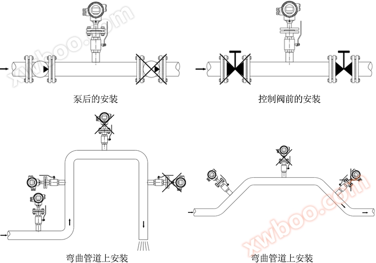  
| 2. Installation conditions |
| 2.1 Straight pipe section |
The use of straight pipe sections can prevent the medium from generating eddy currents or distortions due to the influence of bent pipes, TT type tees, globe valves, and variable diameter pipes 
| 3. Grounding |
| The flowmeter must be grounded according to regulations to ensure reliable operation and prevent operators from receiving electric shock. |

4. Installation insertion depth calculation and instructions
| a. The insertion depth (h) is 1/10 of the inner diameter (D) of the pipeline. |
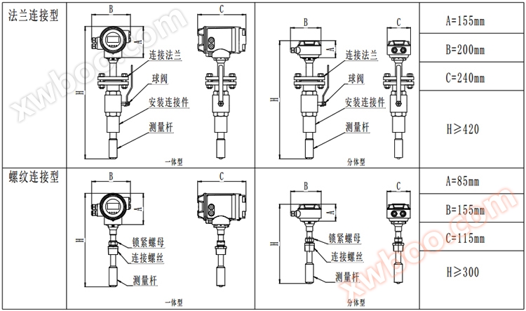
| b. Due to its installation principle, the threaded connection type plug-in electromagnetic needs to manually adjust the size b (the distance from the bottom of the header to the outer wall of the pipeline) during installation to ensure that the insertion depth (h) is 1/10 of the inner diameter (D) of the pipeline. Calculation formula for dimension b: b (distance from the bottom of the header to the outer wall of the pipeline)=H (total length of the product) - A (header height) - h (insertion depth) - c (pipeline wall thickness). |
| c. Before installing the sensor, gently and carefully wipe off any grease, dust, or other dirt on the surface of the sensor's measuring head with an alcohol cotton ball or clean gauze. But hard objects must not be used to damage the electrode surface and insulation materials. |
| d. When the production equipment does not allow interruption of flow, it can be installed under pressure. Firstly, weld the installation connector directly to the installation position of the measuring pipeline, then install the ball valve, and use a dedicated pipeline drilling machine to perform pressurized drilling. After the hole is drilled, close the ball valve to prevent fluid leakage. Then, connect the seal and install the sensor. (Only applicable to flange connection type plug-in electromagnetic) |
| 5. Wiring Guide |
| 5.1 Tips |
| a. The wiring of the electromagnetic flow converter must be completed by professional technicians! |
| b. All wiring should be done after cutting off the power supply; Connect correctly and securely according to the instructions! |
| c. Tighten the compression nut and end cap of the outlet sleeve to maintain a good seal of the converter; |
| d. Surge suppression devices should be installed on lines that are susceptible to lightning surges! |
| e. Before powering on, all wiring should be checked again for accuracy and correctness! |
5.2 Wiring terminals and labeling of integrated converters
| 5.3 Wiring terminals and labeling of split converters |
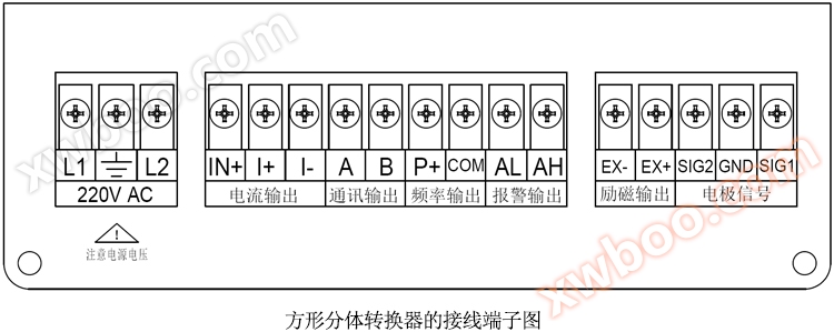
| 5.4 Important Instructions for Wiring |
| Important information about active and passive 4-20mA!!! |
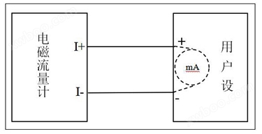
| The electromagnetic flowmeter is a 4-wire instrument that is different from the two-wire instrument's 4-20mA. The two-wire 4-20mA instrument requires an ammeter to be measured and an external 24V power supply to work properly. However, the electromagnetic flowmeter itself is a 4-wire 4-20mA instrument that already has a 24V power supply inside and does not require an external connection. It only needs to be connected to a simple ammeter. Without special customization instructions, our company's electromagnetic flow meters are all active 4-20mA and do not require an external 24V power supply, otherwise the instrument will be burned out. |
| |
| ① Integrated electromagnetic flowmeter active 4-20mA output wiring (by default, the integrated electromagnetic flowmeter is active 4-20mA, and the user equipment ammeter cannot have power output) |
|
② Passive 4-20mA output wiring of integrated electromagnetic flowmeter (Passive 4-20mA of integrated electromagnetic flowmeter needs to be specified when ordering, otherwise it is an active 4-20mA output) |
 |
|
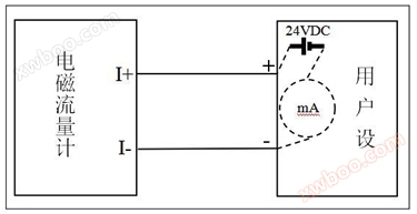 |
| ③ Active 4-20mA output wiring of split electromagnetic flowmeter (split electromagnetic flowmeter does not require special customization and supports both active and passive 4-20mA) |
|
④ Passive 4-20mA output wiring of split electromagnetic flowmeter (split electromagnetic flowmeter does not require special customization and supports both active and passive 4-20mA) |
 |
|
 |
| ⑤ How does the user device determine whether active current output or passive current output is required? |
| a. Disconnect the 4-20mA connection wire between the electromagnetic flowmeter and the user equipment to ensure that the user equipment is in an open circuit state. |
| b. Use a digital multimeter to measure whether the 4-20mA connection line of the user device has a voltage of around 24V. |
| c. If there is a voltage of around 24V, passive current output is required; otherwise, active current output is required; |
|
|
|
|
|
|

|
| 1. Maintenance |
| Sensors generally do not require regular maintenance. But for situations where the measured medium is prone to causing scaling on the surface or inner wall of the electrode and measuring head (measuring tube), regular cleaning is necessary. The cleaning cycle depends on the degree of adhesion and scaling. When cleaning electrodes and measuring heads (measuring tubes), be sure not to damage the insulation material and electrodes. |
2 . Common troubleshooting reference table
| Fault phenomenon |
cause |
Troubleshooting |
| Converter flow is negative |
1. The sensor direction indicator plug is opposite to the fluid flow direction |
1. Rotate the sensor direction 180 ° |
| 2. Adjust the "Flow Direction Options" in the converter |
| Converter output exceeds the range |
1. The flow measurement value is less than the actual measurement value |
1. Expand the range of the flowmeter |
| 2. The fluid is not filled in the pipeline |
2. Turn down the flow control valve |
| 3. Open circuit of excitation coil |
3. Reconnect the wires |
| The output signal fluctuates too much |
1. There is gas present at the sensor electrode, causing poor contact between the electrode and the medium |
1. Remove gas from the pipeline |
| 2. Sediments on the electrode |
2. Clean the electrodes |
| The output signal gradually drifts towards zero value |
1. Sensor water ingress |
1. Replace the sensor |
| 2. The electrode is covered |
2. Clean the electrodes |
The left and right voltages require a constant passive current output, otherwise an active current output is required; |
|
 |
|
|


