|
Setting up a vortex generator (blocking fluid) in the fluid and alternately generating regular vortices from both sides of the vortex generator is called a Karman vortex street, as shown in Figure 1. The vortices are arranged asymmetrically downstream of the vortex generator. Assuming the frequency of vortex occurrence is f, the average velocity of the incoming flow of the measured medium is U, the width of the vortex generator face is d, and the diameter of the body is D, according to the principle of Karman vortex street, there is the following relationship:
|
| In the formula: |
 - Average flow velocity on both sides of the vortex generator, m/s - Average flow velocity on both sides of the vortex generator, m/s |
 Strouhal number Strouhal number |
 The ratio of the bow shaped area on both sides of the vortex generator to the cross-sectional area of the pipeline The ratio of the bow shaped area on both sides of the vortex generator to the cross-sectional area of the pipeline |
 |
 |
| Kaman Vortex Street |
| |
InstantTime volume flow rate For: For:
|
 |
| In the formula, K represents the instrument coefficient of the flowmeter, with pulse count in m3 (P/m3) |
| |
K is not only related to the geometric dimensions of the vortex generator and pipeline, but also to the Strouhal number. The Strouhal number is a dimensionless parameter that is related to the shape of the vortex generator and the Reynolds number. Figure 2 shows the relationship between the Strouhal number of a cylindrical vortex generator and the Reynolds number of a pipeline |
| As shown in the figure, within the range of Re=2 × 10⁴~7 × 10⁶, St can be regarded as a constant, which is the normal operating range of the instrument |
|
 |
| The relationship curve between Strouhal number and Reynolds number |
 |
 |
 |
| 1. Converter 2. Support rod 3. Sensor housing 4. Detection element 5. Vortex generator 6. Temperature and pressure compensation device (including: temperature sensor, pressure sensor, shut-off valve, condenser bend) |
 |
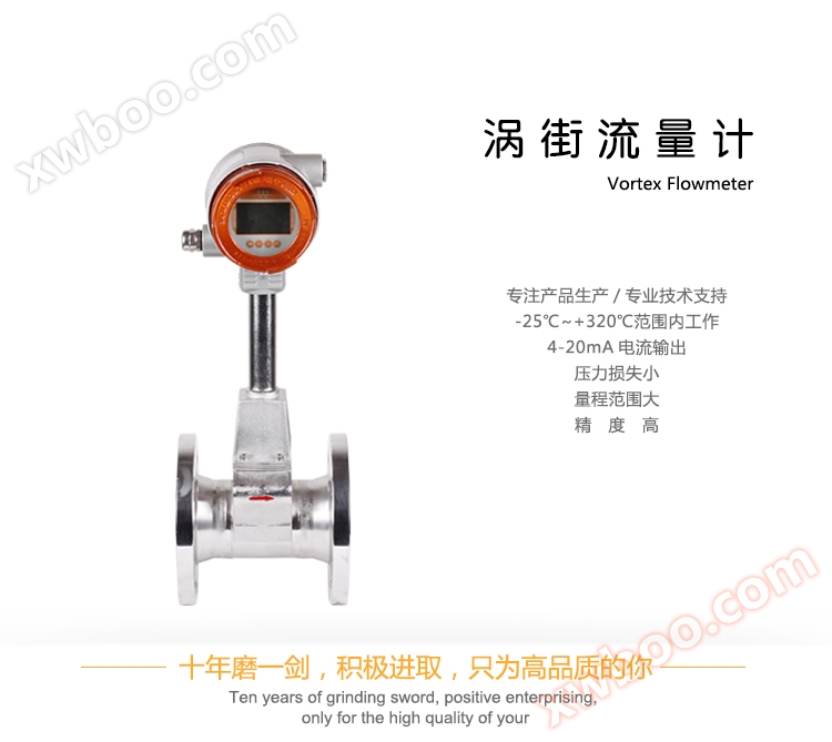
| 1. Small pressure loss, large range, and high accuracy; |
| When measuring the volumetric flow rate under working conditions, it is almost unaffected by parameters such as fluid density, pressure, temperature, viscosity, etc; |
| 3. No movable mechanical parts, therefore high reliability and low maintenance; |
| 4. The instrument parameters can remain stable for a long time. This instrument adopts a piezoelectric stress sensor with high reliability and can operate within a temperature range of -25 ℃ to+320 ℃; |
| 5. It has a wide range of applications and can measure the flow rates of fluids such as steam, gas, and liquid; |
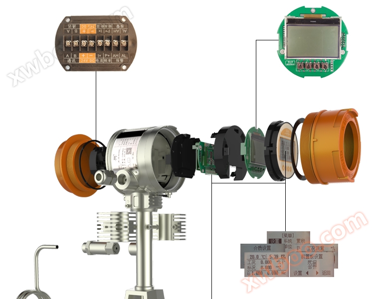
| 6. Humanized menu and interface based on dot matrix display, with bright backlight, supporting both Chinese and English languages, suitable for various customer groups; |
| 7. Support temperature and pressure measurement, convenient for gas medium temperature and pressure compensation needs; |
| 8. Support flow rate conversion display function, convenient for on-site viewing of current flow rate; |
| 9. Support split screen display function, which can enlarge and display single or two parameters (temperature, pressure, operating conditions, flow rate and flow rate under standard conditions, etc.) on the screen; |
| 10. Simulation output function, supporting 4-20mA current simulation and frequency output simulation, convenient for on-site non real current debugging; |
| 11. Supports 4-20mA output, pulse (equivalent) output, alarm output, RS485 communication output; |
| Both two-wire and three wire systems have DCDC (DC1000V) isolation; |
|
 |
| 1. Main technical parameters |
| Measurement medium |
Gas, liquid, steam |
| Execution standards |
Vortex flow sensor (JB/T 9249-1999) |
| Verification regulations |
Vortex flowmeter (JJG 1029-2007) |
| Connection method |
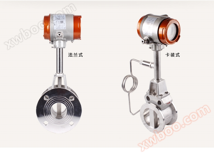
Card mounted, flange mounted |
| Nominal diameter |
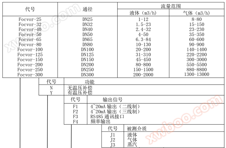
DN25、DN32、DN40、DN50、DN65、DN80、DN100、DN125、DN150、DN200、DN250、DN300 |
| Flange standard |
Conventional standards |
GB/T9113-2000 |
| Other standards |
International pipe flange standard |
Such as German standard DIN, American standard ANSI, Japanese standard JIS |
| Domestic pipe flange standards |
Such as the standards of the Ministry of Chemical Industry and the Ministry of Machinery |
| Verification conditions |
Verification device |
Sonic nozzle flow verification device |
| Accuracy level |
Level 1.5 |
| Range ratio |
1:10 |
| Flow velocity range |
Liquid: 0.5-7m/s Gas: 5-50m/s |
| Instrument material |
304 stainless steel, 316 stainless steel |
| temperature range |
-25 ℃ to 100 ℃- 25 ℃~+280 ℃- 25℃~+320℃ |
| Pressure level |
1.6MPa, 2.5MPa, 4.0MPa |
| output signal |
Pulse frequency signal |
| Two wire 4-20mA DC current signal |
| 485 communication |
| Power supply |
24V DC |
| Explosion proof grade |
Basic Type: Non Explosion proof Product, Explosion proof Type: Exd Ⅱ BT4 |
| Protection level |
IP65 |
| environment condition |
Environmental temperature: -25 ℃~55 ℃ Relative humidity: 5~90% Atmospheric pressure: 86~106KPa |
|
| |
| 2. Flow range of liquid and working gas |
| Diameter DN (mm) |
Liquid (m3/h) |
Gas (m3/h) |
Diameter DN (mm) |
Liquid (m3/h) |
Gas (m3/h) |
| 25 |
1~12 |
8~80 |
100 |
20~200 |
140~1400 |
| 32 |
1.5~23 |
15~150 |
125 |
31~310 |
220~2200 |
| 40 |
2.4~32 |
23~230 |
150 |
45~450 |
300~3000 |
| 50 |
6.3~84 |
35~350 |
200 |
80~800 |
550~5500 |
| 65 |
10~130 |
60~600 |
250 |
150~1500 |
880~8800 |
| 80 |
10~130 |
90~900 |
300 |
200~2000 |
1300~13000 |
|
| |
| 3. Density of commonly used gas media under standard conditions (0.1013mbar, 20 ℃) |
| Gas |
Density (Kg/m3) |
Gas |
Density (Kg/m3) |
Gas |
Density (Kg/m3) |
| acetylene |
1.083 |
N-butane |
2.1463 |
ethane |
1.2500 |
| ammonia |
0.7080 |
ethylene |
1.1660 |
methane |
0.6669 |
| propane |
1.8332 |
neon |
0.83914 |
Natural gas |
0.776 |
| air |
1.2041 |
argon |
1.6605 |
carbon dioxide |
1.829 |
| carbon monoxide |
1.165 |
hydrogen |
0.0838 |
oxygen |
1.3302 |
| propylene |
1.7459 |
nitrogen |
1.1646 |
|
|
|
| |
| 4. Saturated vapor density table |
| Gauge pressure (MPa) |
Temperature (℃) |
Density (kg/m3) |
Gauge pressure (MPa) |
Temperature (℃) |
Density (kg/m3) |
| 0.1 |
120.23 |
1.129 |
1.0 |
184.15 |
5.641 |
| 0.2 |
133.54 |
1.651 |
1.1 |
187.96 |
6.127 |
| 0.3 |
143.62 |
2.163 |
1.3 |
195.04 |
7.106 |
| 0.4 |
151.84 |
2.669 |
1.5 |
201.37 |
8.085 |
| 0.5 |
158.94 |
3.170 |
1.7 |
207.11 |
9.065 |
| 0.6 |
164.96 |
3.667 |
1.9 |
212.37 |
10.05 |
| 0.7 |
170.41 |
4.162 |
2.1 |
217.32 |
11.032 |
| 0.8 |
175.36 |
4.655 |
2.3 |
221.86 |
12.019 |
| 0.9 |
179.88 |
5.147 |
2.5 |
226.11 |
13.011 |
|
| |
| 5. Superheated steam density table |
| cut offPressure P (MPa) |
Temperature t (℃) |
| 100 |
110 |
120 |
130 |
140 |
150 |
160 |
170 |
180 |
| 0.1 |
0.590 |
0.573 |
0.558 |
0.543 |
0.529 |
0.516 |
0.504 |
0.492 |
0.481 |
| 0.2 |
—— |
—— |
1.137 |
1.099 |
1.070 |
1.042 |
1.016 |
0.992 |
0.969 |
| 0.3 |
—— |
—— |
—— |
1.674 |
1.622 |
1.578 |
1.537 |
1.499 |
1.463 |
| 0.4 |
—— |
—— |
—— |
—— |
2.197 |
2.125 |
2.067 |
2.014 |
1.964 |
| 0.5 |
—— |
—— |
—— |
—— |
—— |
2.666 |
2.608 |
2.528 |
2.472 |
| 0.6 |
—— |
—— |
—— |
—— |
—— |
—— |
3.159 |
3.071 |
2.989 |
| 0.7 |
—— |
—— |
—— |
—— |
—— |
—— |
—— |
3.614 |
3.514 |
| 0.8 |
—— |
—— |
—— |
—— |
—— |
—— |
—— |
4.168 |
4.048 |
| 0.9 |
—— |
—— |
—— |
—— |
—— |
—— |
—— |
—— |
4.591 |
| 1.0 |
—— |
—— |
—— |
—— |
—— |
—— |
—— |
—— |
5.145 |
| 1.1 |
—— |
—— |
—— |
—— |
—— |
—— |
—— |
—— |
—— |
| 1.2 |
—— |
—— |
—— |
—— |
—— |
—— |
—— |
—— |
—— |
| 1.3 |
—— |
—— |
—— |
—— |
—— |
—— |
—— |
—— |
—— |
| 1.4 |
—— |
—— |
—— |
—— |
—— |
—— |
—— |
—— |
—— |
| 1.5 |
—— |
—— |
—— |
—— |
—— |
—— |
—— |
—— |
—— |
| 1.6 |
—— |
—— |
—— |
—— |
—— |
—— |
—— |
—— |
—— |
| 1.7 |
—— |
—— |
—— |
—— |
—— |
—— |
—— |
—— |
—— |
| 1.8 |
—— |
—— |
—— |
—— |
—— |
—— |
—— |
—— |
—— |
| 1.9 |
—— |
—— |
—— |
—— |
—— |
—— |
—— |
—— |
—— |
| 2.0 |
—— |
—— |
—— |
—— |
—— |
—— |
—— |
—— |
—— |
| 2.1 |
—— |
—— |
—— |
—— |
—— |
—— |
—— |
—— |
—— |
| 2.2 |
—— |
—— |
—— |
—— |
—— |
—— |
—— |
—— |
—— |
| 2.3 |
—— |
—— |
—— |
—— |
—— |
—— |
—— |
—— |
—— |
| 2.4 |
—— |
—— |
—— |
—— |
—— |
—— |
—— |
—— |
—— |
| 2.5 |
—— |
—— |
—— |
—— |
—— |
—— |
—— |
—— |
—— |
| 2.6 |
—— |
—— |
—— |
—— |
—— |
—— |
—— |
—— |
—— |
| 2.7 |
—— |
—— |
—— |
—— |
—— |
—— |
—— |
—— |
—— |
| 2.8 |
—— |
—— |
—— |
—— |
—— |
—— |
—— |
—— |
—— |
| 2.9 |
—— |
—— |
—— |
—— |
—— |
—— |
—— |
—— |
—— |
| 3.0 |
—— |
—— |
—— |
—— |
—— |
—— |
—— |
—— |
—— |
| 3.1 |
—— |
—— |
—— |
—— |
—— |
—— |
—— |
—— |
—— |
| 3.2 |
—— |
—— |
—— |
—— |
—— |
—— |
—— |
—— |
—— |
| 3.3 |
—— |
—— |
—— |
—— |
—— |
—— |
—— |
—— |
—— |
| 3.4 |
—— |
—— |
—— |
—— |
—— |
—— |
—— |
—— |
—— |
| 3.5 |
—— |
—— |
—— |
—— |
—— |
—— |
—— |
—— |
—— |
| 3.6 |
—— |
—— |
—— |
—— |
—— |
—— |
—— |
—— |
—— |
| 3.7 |
—— |
—— |
—— |
—— |
—— |
—— |
—— |
—— |
—— |
| 3.8 |
—— |
—— |
—— |
—— |
—— |
—— |
—— |
—— |
—— |
| 3.9 |
—— |
—— |
—— |
—— |
—— |
—— |
—— |
—— |
—— |
| 4.0 |
—— |
—— |
—— |
—— |
—— |
—— |
—— |
—— |
—— |
|
| |
|
Absolute pressure P (MPa)) |
Temperature t (℃) |
| 190 |
200 |
210 |
220 |
230 |
240 |
250 |
260 |
270 |
| 0.1 |
0.471 |
0.460 |
0.451 |
0.441 |
0.432 |
0.424 |
0.416 |
0.408 |
0.400 |
| 0.2 |
0.947 |
0.926 |
0.906 |
0.887 |
0.868 |
0.851 |
0.834 |
0.818 |
0.803 |
| 0.3 |
1.428 |
1.396 |
1.365 |
1.336 |
1.308 |
1.281 |
1.256 |
1.231 |
1.208 |
| 0.4 |
1.916 |
1.872 |
1.829 |
1.789 |
1.751 |
1.715 |
1.680 |
1.647 |
1.615 |
| 0.5 |
2.411 |
2.353 |
2.299 |
2.247 |
2.198 |
2.152 |
2.108 |
2.066 |
2.052 |
| 0.6 |
2.912 |
2.841 |
2.773 |
2.710 |
2.650 |
2.593 |
2.539 |
2.487 |
2.438 |
| 0.7 |
3.421 |
3.334 |
3.253 |
3.178 |
3.106 |
3.038 |
2.973 |
2.911 |
2.853 |
| 0.8 |
3.937 |
3.834 |
3.738 |
3.650 |
3.565 |
3.486 |
3.411 |
3.389 |
3.271 |
| 0.9 |
4.461 |
4.342 |
4.230 |
4.127 |
4.029 |
3.939 |
3.852 |
3.769 |
3.691 |
| 1.0 |
4.995 |
4.857 |
4.728 |
4.610 |
4.498 |
4.394 |
4.297 |
4.023 |
4.115 |
| 1.1 |
5.538 |
5.379 |
5.233 |
5.088 |
4.973 |
4.855 |
4.745 |
4.641 |
4.542 |
| 1.2 |
6.089 |
5.909 |
5.745 |
5.593 |
5.452 |
5.321 |
5.197 |
5.082 |
4.972 |
| 1.3 |
6.614 |
6.448 |
6.263 |
6.093 |
5.936 |
5.790 |
5.654 |
5.526 |
5.402 |
| 1.4 |
—— |
6.996 |
6.789 |
6.600 |
6.426 |
6.265 |
6.115 |
5.974 |
5.841 |
| 1.5 |
—— |
7.554 |
7.324 |
7.114 |
6.922 |
6.744 |
6.579 |
6.425 |
6.280 |
| 1.6 |
—— |
—— |
7.866 |
7.635 |
7.423 |
7.229 |
7.049 |
6.880 |
6.723 |
| 1.7 |
—— |
—— |
8.418 |
8.163 |
7.931 |
7.719 |
7.522 |
7.340 |
7.169 |
| 1.8 |
—— |
—— |
8.978 |
8.699 |
8.446 |
8.214 |
8.001 |
7.803 |
7.619 |
| 1.9 |
—— |
—— |
9.549 |
9.234 |
8.967 |
8.715 |
8.484 |
8.271 |
8.072 |
| 2.0 |
—— |
—— |
—— |
9.795 |
9.485 |
9.222 |
8.973 |
8.743 |
8.529 |
| 2.1 |
—— |
—— |
—— |
10.356 |
10.030 |
9.735 |
9.466 |
9.219 |
8.990 |
| 2.2 |
—— |
—— |
—— |
10.927 |
10.573 |
10.255 |
9.965 |
9.700 |
9.455 |
| 2.3 |
—— |
—— |
—— |
11.507 |
11.124 |
10.781 |
10.470 |
10.186 |
9.924 |
| 2.4 |
—— |
—— |
—— |
—— |
11.683 |
11.313 |
10.980 |
10.676 |
10.397 |
| 2.5 |
—— |
—— |
—— |
—— |
12.250 |
11.853 |
11.496 |
11.172 |
10.875 |
| 2.6 |
—— |
—— |
—— |
—— |
12.827 |
12.401 |
12.019 |
11.673 |
11.356 |
| 2.7 |
—— |
—— |
—— |
—— |
13.414 |
12.957 |
12.547 |
12.179 |
11.843 |
| 2.8 |
—— |
—— |
—— |
—— |
—— |
13.519 |
13.082 |
12.690 |
12.334 |
| 2.9 |
—— |
—— |
—— |
—— |
—— |
14.090 |
13.624 |
13.208 |
12.830 |
| 3.0 |
—— |
—— |
—— |
—— |
—— |
14.671 |
14.174 |
13.731 |
13.331 |
| 3.1 |
—— |
—— |
—— |
—— |
—— |
15.260 |
14.731 |
14.260 |
13.837 |
| 3.2 |
—— |
—— |
—— |
—— |
—— |
15.859 |
15.295 |
14.796 |
14.348 |
| 3.3 |
—— |
—— |
—— |
—— |
—— |
16.468 |
15.868 |
15.338 |
14.864 |
| 3.4 |
—— |
—— |
—— |
—— |
—— |
—— |
16.448 |
15.887 |
15.387 |
| 3.5 |
—— |
—— |
—— |
—— |
—— |
—— |
17.037 |
16.442 |
15.914 |
| 3.6 |
—— |
—— |
—— |
—— |
—— |
—— |
17.636 |
17.007 |
16.447 |
| 3.7 |
—— |
—— |
—— |
—— |
—— |
—— |
18.245 |
17.578 |
16.990 |
| 3.8 |
—— |
—— |
—— |
—— |
—— |
—— |
18.861 |
18.155 |
17.535 |
| 3.9 |
—— |
—— |
—— |
—— |
—— |
—— |
19.489 |
18.741 |
18.087 |
| 4.0 |
—— |
—— |
—— |
—— |
—— |
—— |
—— |
19.335 |
18.646 |
|
| |
| Absolute pressure P (MPa) |
Temperature t (℃) |
| 280 |
290 |
300 |
310 |
320 |
330 |
340 |
350 |
| 0.1 |
0.393 |
0.386 |
0.379 |
0.372 |
0.366 |
0.360 |
0.354 |
0.348 |
| 0.2 |
0.788 |
0.774 |
0.760 |
0.747 |
0.734 |
0.721 |
0.709 |
0.698 |
| 0.3 |
1.185 |
1.163 |
1.142 |
1.122 |
1.103 |
1.084 |
1.066 |
1.049 |
| 0.4 |
1.585 |
1.555 |
1.527 |
1.500 |
1.474 |
1.449 |
1.424 |
1.400 |
| 0.5 |
1.986 |
1.949 |
1.914 |
1.879 |
1.846 |
1.815 |
1.784 |
1.754 |
| 0.6 |
2.391 |
2.345 |
2.302 |
2.260 |
2.220 |
2.182 |
2.145 |
2.109 |
| 0.7 |
2.797 |
2.743 |
2.693 |
2.643 |
2.596 |
2.551 |
2.507 |
2.465 |
| 0.8 |
3.206 |
3.145 |
3.085 |
3.028 |
2.974 |
2.921 |
2.871 |
2.822 |
| 0.9 |
3.608 |
3.547 |
3.479 |
3.405 |
3.352 |
3.293 |
3.236 |
3.181 |
| 1.0 |
4.032 |
3.952 |
3.876 |
3.804 |
3.734 |
3.667 |
3.602 |
3.541 |
| 1.1 |
4.448 |
4.359 |
4.275 |
4.195 |
4.117 |
4.042 |
3.971 |
3.902 |
| 1.2 |
4.869 |
4.771 |
4.675 |
4.587 |
4.500 |
4.419 |
4.304 |
4.264 |
| 1.3 |
5.291 |
5.181 |
5.079 |
4.980 |
4.888 |
4.789 |
4.710 |
4.630 |
| 1.4 |
5.718 |
5.596 |
5.485 |
5.376 |
5.274 |
5.179 |
5.084 |
4.995 |
| 1.5 |
6.143 |
6.013 |
5.893 |
5.777 |
5.666 |
5.559 |
5.459 |
5.362 |
| 1.6 |
6.575 |
6.435 |
6.301 |
6.177 |
6.057 |
5.942 |
5.834 |
5.730 |
| 1.7 |
7.008 |
6.859 |
6.716 |
6.579 |
6.541 |
6.329 |
6.211 |
6.099 |
| 1.8 |
7.446 |
7.283 |
7.133 |
6.983 |
6.849 |
6.716 |
6.592 |
6.470 |
| 1.9 |
7.886 |
7.710 |
7.547 |
7.391 |
7.246 |
7.102 |
6.969 |
6.843 |
| 2.0 |
8.333 |
8.143 |
7.968 |
7.800 |
7.645 |
7.496 |
7.353 |
7.217 |
| 2.1 |
8.777 |
8.578 |
8.391 |
8.214 |
8.047 |
7.888 |
7.737 |
7.593 |
| 2.2 |
9.227 |
9.015 |
8.816 |
8.628 |
8.451 |
8.283 |
8.123 |
7.970 |
| 2.3 |
9.681 |
9.455 |
9.244 |
9.045 |
8.679 |
8.510 |
8.349 |
8.349 |
| 2.4 |
10.139 |
9.899 |
9.675 |
9.464 |
9.265 |
9.078 |
8.899 |
8.729 |
| 2.5 |
10.061 |
10.347 |
10.108 |
9.886 |
9.676 |
9.478 |
9.290 |
9.112 |
| 2.6 |
11.066 |
10.797 |
10.545 |
10.310 |
10.089 |
9.880 |
9.680 |
9.495 |
| 2.7 |
11.534 |
11.250 |
10.984 |
10.737 |
10.504 |
10.285 |
10.078 |
9.880 |
| 2.8 |
12.008 |
11.706 |
11.427 |
11.167 |
10.922 |
10.962 |
10.473 |
10.267 |
| 2.9 |
12.484 |
12.167 |
11.872 |
11.598 |
11.342 |
11.100 |
10.872 |
10.656 |
| 3.0 |
12.967 |
12.630 |
12.321 |
12.034 |
11.765 |
11.511 |
11.273 |
11.047 |
| 3.1 |
13.542 |
13.099 |
12.773 |
12.470 |
12.189 |
11.925 |
11.674 |
11.439 |
| 3.2 |
13.941 |
13.570 |
13.229 |
12.912 |
12.617 |
12.340 |
12.079 |
11.833 |
| 3.3 |
14.436 |
14.047 |
13.687 |
13.355 |
13.046 |
12.757 |
12.484 |
12.228 |
| 3.4 |
14.937 |
14.526 |
14.148 |
13.801 |
13.479 |
13.177 |
12.893 |
12.626 |
| 3.5 |
15.439 |
15.008 |
14.616 |
14.251 |
13.914 |
13.598 |
13.303 |
13.025 |
| 3.6 |
15.949 |
15.497 |
15.073 |
14.704 |
14.351 |
14.023 |
13.716 |
13.426 |
| 3.7 |
16.464 |
15.990 |
15.557 |
15.158 |
14.791 |
14.449 |
14.130 |
13.829 |
| 3.8 |
19.984 |
16.485 |
16.033 |
15.618 |
15.235 |
14.879 |
14.546 |
14.235 |
| 3.9 |
17.507 |
16.997 |
16.513 |
16.080 |
15.681 |
15.312 |
14.966 |
14.641 |
| 4.0 |
18.038 |
17.492 |
16.998 |
16.545 |
16.129 |
15.746 |
15.387 |
15.049 |
|
 |
| The Focvor series vortex flowmeter has two connection methods and external dimensions |
|

|
| name |
orifice |
pressure rating |
Total length |
Height |
Width |
Temperature pressure distance |
flange outer diameter |
Outer diameter of shell |
Center distance of bolt holes |
Quantity and aperture |
| DN |
Mpa |
L |
G1 |
G2/G3 |
G4 |
D |
d |
K |
N*L |
| Card mounted unit (mm) |
25 |
4.0 |
90 |
430 |
235 |
145 |
—— |
Φ57 |
—— |
—— |
| 32 |
4.0 |
90 |
435 |
235 |
145 |
—— |
Φ65 |
—— |
—— |
| 40 |
4.0 |
90 |
440 |
235 |
145 |
—— |
Φ75 |
—— |
—— |
| 50 |
4.0 |
90 |
460 |
235 |
145 |
—— |
Φ87 |
—— |
—— |
| 65 |
1.6 |
90 |
475 |
240 |
150 |
—— |
Φ109 |
—— |
—— |
| 80 |
1.6 |
100 |
510 |
240 |
150 |
—— |
Φ120 |
—— |
—— |
| 100 |
1.6 |
100 |
530 |
250 |
160 |
—— |
Φ149 |
—— |
—— |
| 125 |
1.6 |
100 |
555 |
290 |
200 |
—— |
Φ175 |
—— |
—— |
| 150 |
1.6 |
100 |
585 |
330 |
230 |
—— |
Φ203 |
—— |
—— |
| 200 |
|
|
|
|
|
—— |
|
—— |
—— |
| 250 |
|
|
|
|
|
—— |
|
—— |
—— |
| 300 |
|
|
|
|
|
—— |
|
—— |
—— |
| Flange unit (mm) |
25 |
4.0 |
170 |
460 |
235 |
145 |
Φ115 |
—— |
Φ85 |
4×Φ14 |
| 32 |
4.0 |
174 |
475 |
235 |
145 |
Φ140 |
—— |
Φ100 |
4×Φ18 |
| 40 |
4.0 |
180 |
480 |
235 |
145 |
Φ150 |
—— |
Φ110 |
4×Φ18 |
| 50 |
4.0 |
186 |
500 |
235 |
145 |
Φ165 |
—— |
Φ125 |
4×Φ18 |
| 65 |
1.6 |
186 |
515 |
240 |
150 |
Φ185 |
—— |
Φ145 |
4×Φ18 |
| 80 |
1.6 |
200 |
550 |
250 |
150 |
Φ200 |
—— |
Φ160 |
8×Φ18 |
| 100 |
1.6 |
204 |
565 |
270 |
160 |
Φ220 |
—— |
Φ180 |
8×Φ18 |
| 125 |
|
|
|
|
|
|
—— |
|
|
| 150 |
|
|
|
|
|
|
—— |
|
|
| 200 |
|
|
|
|
|
|
—— |
|
|
| 250 |
|
|
|
|
|
|
—— |
|
|
| 300 |
|
|
|
|
|
|
—— |
|
|
|
 |
|
|
 |
| 1. Wiring terminal diagram |
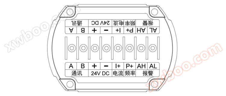 |
| 2. Meaning of wiring terminals |
| communication |
A |
RS485 communication A |
| B |
RS485 communication B |
| 24V DC |
+ |
24V DC power input (positive) |
| - |
24V DC power input (negative) |
| electric current |
I+ |
4~20mA output |
| frequency |
P+ |
24V frequency, pulse output |
| call the police |
AH |
Upper limit alarm output |
| AL |
Lower limit alarm output |
|
| 3. Wiring diagram |
| ① Two wire 4-20mA output |
|
② Three wire system with 4-20mA output |
 |
|
 |
| ③ 24V frequency, pulse output |
|
④ RS485 communication interface output |
| Note: The negative terminal of frequency output and the negative terminal of DC 24V are common terminals; The frequency and pulse output must be wired according to a three wire system, as shown in the diagram below. The two-wire system does not support frequency and pulse output; The default factory frequency and pulse output are active outputs; The default factory frequency and pulse output idle level are high level, and low level when pulses are received. |
|
Note: RS485 communication must be wired according to a three wire system, as shown in the diagram below. Two wire system does not support RS485 communication. |
 |
|
 |
| ⑤ Alarm signal output |
|
⑥ Power supply |
| Note: The alarm output must be wired according to the three wire system, as shown in the diagram below. The two wire system does not support alarm output. |
|
| When the flow meter requires flow pulse signal output, an external power supply with a supply voltage of+24V DC is required (Three line system). |
| When the flowmeter requires a 4-20mA current signal output, a+24V DC external power supply (two-wire or three wire system) needs to be added. |
| When the flowmeter requires RS485 data communication, a+24V DC power supply needs to be added. (Three line system). |
|
 |
|
| 4. Electrical characteristics |
| ① Two wire system: The maximum value is 26V DC, and the minimum value depends on the load, |
| The conversion formula is: RL=(Umin-17)/0.022, Umin=RL * 0.022+17 |
| Where RL is the load resistance, measured in ohms; Umin is the minimum supply voltage, measured in volts, and should not exceed a maximum of 26V DC. |
| For example, for a 250 Ω load, the minimum supply voltage Umin is 250 * 0.022+17=22.5V. |
| ② Three wire system: power supply range: 12-26V DC; Power: 940mW MAX @ 26V DC |
|
 |
| Vortex flow meters are sensitive to flow velocity distribution distortion, rotational flow, and flow pulsation in pipelines. Therefore, the installation conditions of pipelines on site should be fully taken into account, and the requirements of the manufacturer's instructions should be followed. |
| Vortex flow meters are sensitive to flow velocity distribution distortion, rotational flow, and flow pulsation in pipelines. Therefore, the installation conditions of pipelines on site should be fully taken into account, and the requirements of the manufacturer's instructions should be followed. Vortex flowmeter can be installed indoors or outdoors. If installed in underground wells, there is a possibility of flooding, and submersible sensors should be selected. Sensors can be installed horizontally, vertically, or obliquely on pipelines, but when measuring liquids and gases, attention should be paid to the installation position to prevent interference from bubbles and droplets. |
| 1. Installation of mixed phase fluids |
 |
| (a) Installation of flow meters for measuring gases containing liquids; (b) Installation of measuring gas-liquid flow meter |
|
| 2. Requirements for downstream straight pipe length of vortex flowmeter |
 |
| (a) A 90 ° elbow; (b) Concentric expansion tube; (c) Concentric contraction fully open valve; (d) Two 90 ° elbows on different planes; (e) Half open regulating valve; (f) Two 90 ° elbows on the same plane |
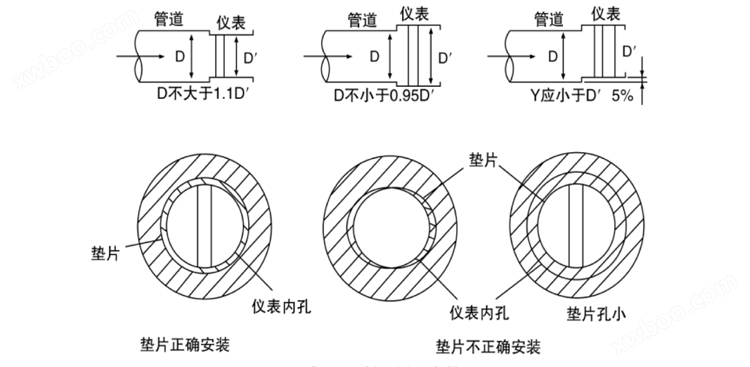
| 3. Connection between sensors and pipelines |
 |
| 4. Schematic diagram of bypass pipeline |
| 1) The inner diameter D of the upstream and downstream piping is the same as the inner diameter D 'of the sensor, and the difference satisfies the following condition: 0.95D ≤ D' ≤ 1.1D. |
| 2) The piping should be concentric with the sensor, and the coaxiality should not be less than 0.05D '. |
| 3) The sealing gasket cannot protrude into the pipeline, and its inner diameter can be 1-2mm larger than the inner diameter of the sensor. |
| 4) If it is necessary to cut off the flow for inspection and cleaning of the sensor, a bypass pipeline should be set up as shown in the figure. |
 |
| 5. Example of installing pipeline support |
| The impact of dynamic sources on vortex flowmeters should be addressed as a prominent issue in the on-site installation of vortex flowmeters. Firstly, when selecting the installation location for sensors, try to avoid vibration sources as much as possible. Secondly, elastic hoses can be used for connection, which can be considered for small diameters. Thirdly, installing pipeline supports is an effective vibration reduction method, as shown in the figure. |
 |
| 6. Electrical installation should pay attention to using shielded cables or low-noise cables to connect sensors and converters. When wiring, it should be kept away from high-power power lines and protected with separate metal sleeves as much as possible. The principle of "one point grounding" should be followed, and the grounding resistance should be less than 10 Ω. Both integral and separated types should be grounded on the sensor side, and the grounding point of the converter housing should be "same ground" as the sensor. |
 |
| Fault phenomenon |
Possible reasons |
processing method |
| When there is no flow after power on, there is an output signal |
1. Poor input shielding or grounding introduces electromagnetic interference |
1. Improve shielding and grounding to eliminate electromagnetic interference |
| 2. The instrument is located near strong electrical equipment or high-frequency pulse interference sources |
2. Install away from interference sources and take isolation measures to strengthen power filtering |
| 3. The pipeline has strong vibration. 3. The pipeline has strong vibration |
3. Adopt limited shock absorption measures. |
| No output signal after passing current |
1. Power supply malfunction |
1. Check the power supply and grounding |
| 2. The incoming signal line is disconnected |
2. Check the signal wires and wiring terminals |
| 3. No traffic or low traffic |
3. Check the sensing components and leads, inspect the valve, increase the flow rate or decrease the pipe diameter |
| 4. Pipeline blockage or sensor jamming |
4. Check and clean the pipeline, clean the sensor |
| The output signal is irregular and unstable |
1. There is a strong electrical interference signal |
1. Strengthen shielding and grounding |
| 2. The sensor is contaminated or damp, resulting in a decrease in sensitivity |
2. Clean or replace the sensor to increase the amplifier gain |
| 3. Sensor damage or poor lead contact |
3. Check the sensors and leads |
| 4. Two phase flow or pulsating flow occurs |
4. Strengthen process management and eliminate two-phase flow or pulsating flow phenomena |
| 5. The impact of pipeline vibration |
5. Adopt limited shock absorption measures |
| 6. Unstable process flow |
6. Adjust the installation position |
| 7. Sensor installation is not concentric or the sealing gasket protrudes into the pipe |
7. Check the installation condition and correct the inner diameter of the sealing gasket |
| 8. Upstream and downstream valve disturbance |
8. Extend the straight pipe section or install a flow regulator |
| 9. Fluid not filling the pipeline |
9. Change the location and method of installing the flow sensor |
| 10. There are entanglements in the body that occur |
10. Eliminate entanglement |
| 11. Existence of air pockets |
11. Reduce the flow rate and increase the pressure inside the pipe |
| Leakage of measuring tube |
1. Excessive pressure inside the pipe |
1. Adjust the pipe pressure and change the installation position |
| 2. Incorrect selection of nominal pressure |
2. Choose a higher-level nominal pressure sensor |
| 3. The seal is damaged and the sensor is corroded |
3. Replace the sealing components and take anti-corrosion and protective measures |
| Large measurement error |
1. Insufficient length of straight pipe section |
1. Extend the straight pipe section or install a flow regulator |
| 2. Incorrect zero drift or full-scale adjustment of analog conversion circuit |
2. Calibrate zero and range scales |
| 3. Excessive changes in power supply voltage |
3. Check the power supply |
| 4. The instrument exceeds the calibration cycle |
4. Timely submission for inspection |
| 5. There is a significant difference in the inner diameter between the sensor and the piping |
5. Check the inner diameter of the piping and correct the instrument coefficient |
| 6. Install non concentric or gasket protruding into the pipe |
6. Adjust the installation and repair the sealing gasket |
| 7. Sensor contamination or damage |
7. Clean and replace the sensor |
| 8. There is two-phase flow or pulsating flow |
8. Exclude two-phase flow or pulsating flow |
| 9. Pipeline leakage |
9. Eliminate leaks |
| The sensor emits an abnormal whistling sound |
1. Excessive flow velocity causes strong vibration |
1. Adjust the flow rate or replace the instrument with a larger diameter |
| 2. Generating cavitation phenomenon |
2. Adjust the flow rate and increase the liquid flow pressure |
| 3. Body loosening occurs |
3. Tighten the generator |
|
| 1) Users are not allowed to change the wiring method of the explosion-proof system or arbitrarily twist various output line connectors. |
| 2) When the flowmeter is running, it is not allowed to arbitrarily open the front cover to change the instrument parameters, otherwise it will affect the normal operation of the flowmeter. |
| 3) Do not loosen the fixed part of the flowmeter at will. |
| 4) When using the product outdoors, it is recommended to add a waterproof device. |
 |
 |
 |
 |
|
 |
 |
 |
| |
| |
| |
| |
| |


